Accelerometer X-Y-Z
Get measurement of linear acceleration along the X, Y, and Z axes of the Accelerometer
Since R2023b
Libraries:
Simulink Coder Support Package for BBC
micro:bit/Accelerometer
Description
The Accelerometer X-Y-Z block measures the linear acceleration along the
X, Y, and Z axes. The block has three output ports. The Accel port outputs the acceleration
from the as a [1x3] vector in g (9.8
m/s2).
Using the parameters of this block, you can change the accelerometer sensitivity by
selecting a full-scale range of ±2 g, ±4 g, or
±8 g.
You can also select the Output Data Rates (ODR) for both of the sensors. The Output Data
Rates (ODR) ranges from 1.5625 Hz to 800 Hz.
The Accelerometer X-Y-Z block supports BBC micro:bit board versions V1.3, V1.5, and V2.2.
This block consists of Freescale MMA8653FC and LSM303AGR 3-axes Accelerometer sensors.
Note
The LSM303AGR 3-axes Accelerometer sensor supports V1.5, and V2.2 boards and Freescale MMA8653FC sensor supports V1.3 board.
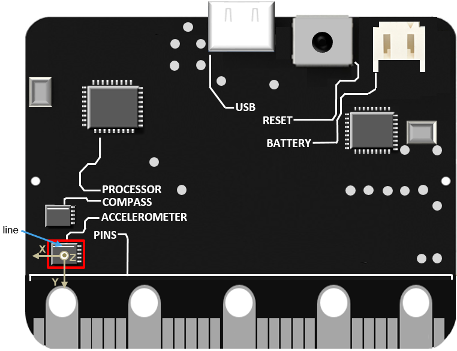
Chip Orientation and Axis Orientation Relative to Gravity
Hold the board so that the board faces you and the line to the top of the MMA8652FC 3-Axis chip is aligned horizontally to the table. At this position, the X-axis is horizontal and points to the left, the Y-axis is vertical and points down, and the Z-axis points toward you.
The direction of the arrows shows the positive direction of the reading for the accelerometer.
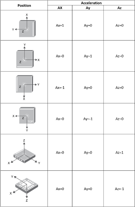
When you tilt the board along the X, Y, and Z axes of the chip, this illustration shows the acceleration.
Hold the board so that the board faces you and the line to the right of the chip is aligned vertically to the table. The acceleration of gravity is static because the chip is stationary.
In the resultant [1x3] vector, the first value that represents
the acceleration at the X-axis ≈1 g (9.81
m/s2). The last two values that represent the
acceleration at the Y and Z axes (perpendicular to the acceleration of earth gravity)
≈ 0.00 g.
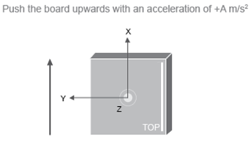
Push the board upward with an acceleration of A
m/s2
. The acceleration of the gravity is dynamic and equal to the acceleration
of the block minus the force of gravity ≈ (+A-9.81)
m/s2
. In the resultant [1x3] vector, the value of the X-axis
ranges between the full-scale range value that you specify in the
Acceleration full scale range parameter.
Ports
Output
Parameters
Version History
Introduced in R2023b