Dice Simulation on LED Matrix
This example shows you how to develop a Simulink® model to implement a Dice Simulation on BBC micro:bit board using the on board Accelerometer sensor and 5x5 LED Matrix.
Introduction
The BBC micro:bit board has a 5x5 LED Matrix and Accelerometer sensor. In this example, you will develop a Simulink model to:
Implement an algorithm on Stateflow®.
Detect the shake of the BBC micro:bit board using the Accelerometer blocks.
Use the LED matrix block and display numbers 1-6 randomly on the LED matrix display based on the shake of BBC micro:bit.
Prerequisites
If you are new to Simulink, we recommend completing the Interactive Simulink Tutorial.
If you are new to Simulink Coder™, visit the Simulink Coder product page for an overview and tutorials.
We also recommend completing Getting Started with Simulink Coder Support Package for BBC micro:bit.
Required Hardware
To run this example you will need the following hardware:
BBC micro:bit board
USB type A to Micro-B cable
Open the bbcmicrobit_shake_dice model.
Task 1 - Implement the Algorithm in Stateflow
In this section, we shall implement the algorithm in Simulink using a Stateflow chart.
1. Create a new Simulink model.
2. Open the Simulink library browser. Add a Stateflow chart from Stateflow > Chart to your model.
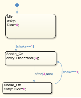
3. In the Stateflow chart, create these three states:
Idle state
Shake_On state
Shake_Off state
4. Define a variable "Dice", which decides which number (1-6) is to be displayed on the LED matrix. Make Dice=0 for Idle state and for the Shake_Off state.
5. For Shake_On state, assign random value 1-6 using the MATLAB® builtin function randi() to the Dice variable.
6. Draw transition lines between these states. Each transition corresponds to different "shake" value (0 or 1) of the accelerator.
7. Shake_On to Shake_Off transition should hold for 3 seconds. After 3 seconds, it should go to Shake_On state if a shake is detected.
The complete algorithm implemented using the Stateflow chart would look similar to the implementation shown here.
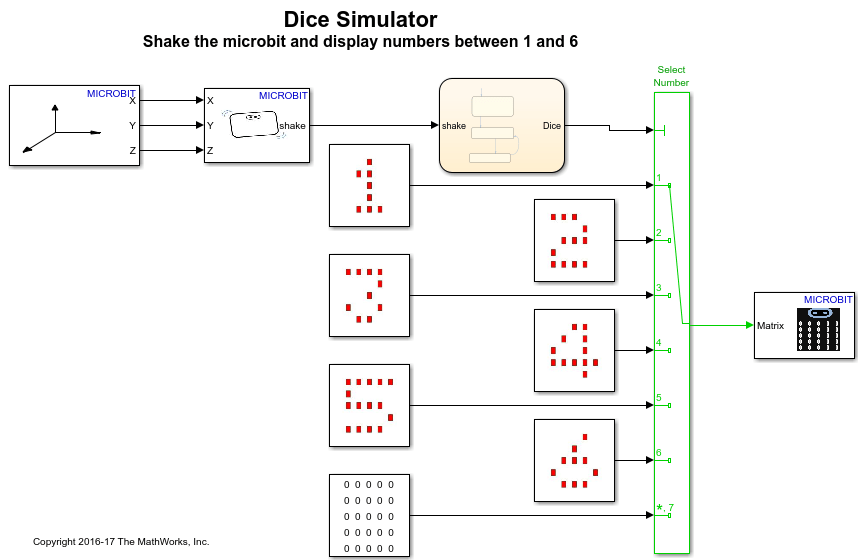
Task 2 - Add Hardware Specific Blocks
In this section, we will add BBC micro:bit specific blocks to the Simulink model that we developed in Task 1.
1. In the Simulink library browser, navigate to the Simulink Coder Support Package for BBC micro:bit library.
2. Add the Accelerometer X-Y-Z block and the Shake Detection block from Simulink Coder Support Package for BBC micro:bit > Accelerometer into your Simulink model.
3. Connect the output of the Accelerometer X-Y-Z block to the Shake Detection block and connect the output of the Shake Detection block to the input of the Stateflow chart.
4. From the library Simulink Coder Support Package for BBC micro:bit > LED > LED Images, add the LED images for 1-6 numbers and one for an empty display. Add Multiport switch from Simulink > Signal Routing and connect the output ports of the image blocks to the data ports of this Multiport switch block. Also, connect the output port of Stateflow to the control port of the Multiport switch.
5. Add the 5x5 LED matrix block from Simulink Coder Support Package for BBC micro:bit > LED into your model, and connect the output of the Multiport switch to this block.
Note: If you are using the BBC micro:bit V2 board, then you must enable the Interrupt for LED Matrix using these steps.
a. In your Simulink model, click Modeling > Model Settings to open the Configuration Parameters dialog.
b. In the Configuration Parameters dialog, select the Hardware Implementation pane, click Target hardware resources > LED Matrix and select Enable for Interrupt option. Click Apply and OK.
A pre-configured model, bbcmicrobit_shake_dice is included for your convenience.
Task 3 - Configure and Run the Dice Simulation Model as a Standalone Application
In this task, you will configure and run your model on the BBC micro:bit.
1. Connect the BBC micro:bit to your computer with a USB cable.
2. In your Simulink model, go to the Modeling tab and click Model Settings.

3. When the Configuration Parameters dialog box opens up, navigate to Hardware Implementation pane.
Set the Hardware board parameter to BBC micro:bit.
On the Target Hardware Resources pane, Set the Build action to Build, load and run to automatically download the generated binary file on to the connected BBC micro:bit.
4. Navigate to Solver pane and set the Solver to discrete (no continuous states).
5. Click OK.
6. In your Simulink model, go to the Hardware tab and click Build, Deploy & Start. The model will now be deployed to the BBC micro:bit.

7. Observe that the image displayed on the LED matrix is random from numbers 1 to 6, on shaking the BBC micro:bit board.
8. Save your model.
Task 4 - (Optional) Configure and Run the Dice Simulation Model for Parameter Tuning
1. Open the bbcmicrobit_shake_dice model.
2. Complete the steps 1-5 in Task 3.
3. In the model, go to the Hardware tab and click Monitor & Tune to run the model on BBC micro:bit board for signal monitoring and parameter tuning.
4. Observe that the image displayed on the LED matrix is random from numbers 1 to 6, on shaking the BBC microbit board.
5. While the model is running, double click the Stateflow chart and observe the state transitions when you shake the BBC micro:bit board. The current state is highlighted with a blue boundary.
6. You can also change the "Sensitivity" parameter of the Shake Detection block to control the sensitivity of the shake. Default value is "3". Reduce it to "2" or "1.5" and observe the difference.
8. Click the Stop icon on the Hardware tab to stop the execution of the model for monitoring and tuning.
Summary
This example showed how to create a Simulink model to implement a Dice Simulation on BBC micro:bit board using the on board Accelerometer sensor and 5x5 LED Matrix.
Accelerometer sensor and the LED Matrix block from the BBC micro:bit library were used to implement this algorithm.
The example showed how the model can be deployed as a standalone application on the BBC micro:bit board, and alternatively, how it can also be run for signal monitoring and parameter tuning.