Widebus Crosstalk Analysis
Widebus crosstalk analysis (pre-layout crosstalk analysis in the Parallel Link Designer app) consists of single transfer sheets (transfer nets) and a widebus or coupled sheet with a victim transfer net and one or more aggressor nets.
For a high speed clock forwarded parallel interface project, widebus crosstalk analysis allows you to:
Generate the layout rules including etch impedance, spacing, length, termination.
Determine operating limits and trade offs (for example. maximum frequency vs line length).
Determine the optimal drive strength and ODT selection.
Determine design margins to timing or mask requirements.

Each unique transfer net on a widebus schematic sheet is known as a widebus group. Each group consists of only the designators (drivers, receivers, or I/O buffers) for that transfer net. On a widebus sheet, any widebus group can be a victim or an aggressor. You can place multiple instances of any widebus group on the schematic. The widebus groups inherit the designator properties defined in their transfer net sheet. You can use coupled w-lines, connectors, package models, or s-parameter blocks in the widebus schematic to connect up each widebus group. One of the instances of a widebus group is designated as the victim net on the schematic.
You can perform widebus crosstalk analysis simulation using STAT mode, where statistical and time domain IBIS-AMI results are used in the waveform and timing analysis. This is referred to as STAT Mode Crosstalk. You can also run the analysis using SPICE only, where all of the results from the coupled sheet simulation (waveform and timing) are derived solely from the SPICE simulations. This is known as the Classic Mode Crosstalk.
You can perform widebus analysis on any project, even previous incarnations of a design. You must satisfy these requirements:
One or more associated sheets (reference transfer nets) exist. The designator grouping on each unique transfer net are referred to as a widebus group.
Each transfer nets consist of a single driver per transfer. They can have multiple transfers (memory read or memory write) and can have multiple receivers/loads.
Transfer net characteristics such as transfers, UI, type, probe points and jitter are defined in the transfer net characteristics on the associated sheet, not on a widebus sheet.
Creating Widebus Sheet
To create a widebus sheet, you must include at least one transfer net in the schematic. From the app toolstrip, add a new schematic sheet from File > Schematic Sheet > New Sheet. In the New Sheet dialog box, select the Widebus sheet option. When you are creating a widebus sheet for the first time, the Add Widebus Group(s) dialog box launches automatically. You can select the widebus groups and their number of instances.
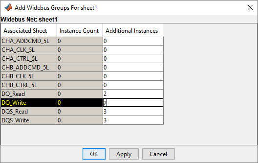
To include additional widebus groups to the sheet, right click and select Add Widebus Group(s). The victim group(s) is designated in yellow on the schematic.
After placing the widebus groups, you can connect the coupled elements for crosstalk analysis. You can edit the widebus group properties to define which group is the victim net along with the stimulus and delay of each group. To edit any widebus group, double click any of the designators on the schematic or right-click and select Widebus Groups.

Simulating Widebus Sheet
You can simulate the widebus in STAT mode by selecting STAT Mode in the Sheet Options panel. To simulate in the classic mode, deselect the STAT Mode option. In the STAT mode, you can select to display the AMI parameters of the Tx aggressors by selecting the Tx Aggressor Parameters option. The simulation process of widebus sheets is the same as that of the uncoupled sheets.
In a widebus simulation, the app performs all waveform and timing analysis on the victim group. As with a regular timing analysis, widebus timing analysis requires a separate clock (or strobe) simulation. This separate clock simulation can come from:
A clock or strobe associated sheet.
A clock or strobe victim group in another widebus sheet.
In the current widebus sheet, select Sweep Victim and select both the clock group and data group as victims.
In the current widebus sheet with a victim group that uses a receiver IBIS-AMI model that supports clock forwarding, select the desired clock or strobe group from the Clock Group drop down menu.
Interpreting results
For the most part, simulating a widebus sheet reports many of the same results as an uncoupled sheet. For each victim transfer on a widebus sheet, results are presented both with and without the effects of the coupling on the victim net. Regardless of crosstalk simulation mode (classic or STAT), the app can perform and report the waveform and timing checks (if selected). If you select the STAT Mode option, the app runs both the statistical and time domain simulations.
Results for widebus sheets only includes the victim widebus group transfers. The app does not report the aggressor results. It only reports the crosstalk from the aggressors on the victim waveform.
After widebus simulation, you can view crosstalk noise as a histogram. This is essentially a statistical eye diagram of the crosstalk noise where colors are associated with the probabilities of the noise and the placement of the noise within the UI of the channel. This crosstalk probability is what is added to the uncoupled victim channel response to get the coupled response.
To view the coupling from the victim to each aggressor, plot the step response or the pulse response. This reveals the level of coupling between the victim and each aggressor. You can also plot the composite crosstalk on each victim in the Signal Integrity Viewer app. To plot the composite crosstalk, in the Statistical tab of the Signal Integrity Viewer app, right click and select Show Crosstalk.