Specify Bus Properties at Component Interfaces
This example shows how to specify bus properties at a model interface by using bus element ports both with and without Simulink.Bus objects.
Open Example Model
To open the IterativeCounter project, open the example. The project opens the CounterSystem model at startup.
To update the line styles, update the model. On the Modeling tab of the Simulink® Toolstrip, click Update Model. You can use the line styles to visually identify buses.
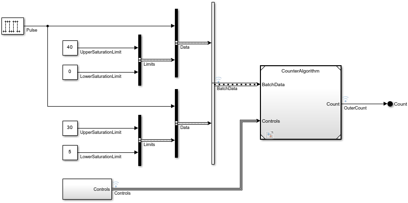
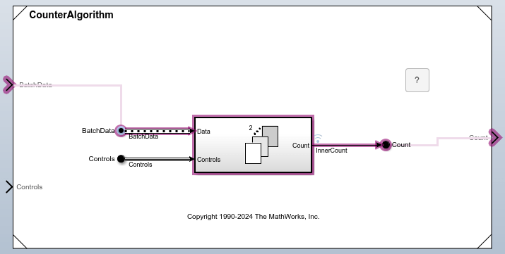
A Model block references the model named CounterAlgorithm. The referenced model receives two inputs:
BatchData— An array of buses that provides the data and the saturation limits of the counter. This array contains two nonvirtual buses namedData. Each of these nonvirtual buses contains a signal namedPulseand a nonvirtual bus namedLimits.Controls— A virtual bus that provides the signals that change the increment, reset the counter, and define an offset for the counter.
The interfaces between the referenced model and parent model must be compatible. Specifications such as data type must match, and elements the referenced model uses must be available from the parent model.
Array of Buses Creation
To create the array of buses, the CounterSystem model uses a Vector Concatenate block.
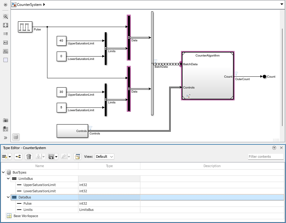
To create the nonvirtual buses, the CounterSystem model uses Bus Creator blocks that specify Simulink.Bus objects. Nonvirtual buses must be defined by Simulink.Bus objects. A data dictionary named BusTypes.sldd provides the Simulink.Bus objects to the model.
DataBus— ASimulink.Busobject that defines the nonvirtual buses namedDatain the array of busesLimitsBus— ASimulink.Busobject that defines the nonvirtual buses namedLimitsin the nonvirtual buses namedData
To view the bus objects and their usage, use the Type Editor. In the Simulink Toolstrip, on the Modeling tab, in the Design gallery, click Type Editor. To highlight the blocks that use a bus object, in the Type Editor, select the bus object. For example, select DataBus. Two Bus Creator blocks and the Model block use this bus object.
Bus Interface Specification with Bus Object
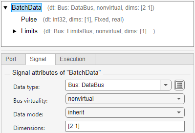
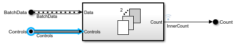
In the CounterAlgorithm model, the In Bus Element block labeled BatchData receives the array of buses.

To define the interface, the port named BatchData specifies:
Data type as
Bus: DataBusBus virtuality as
nonvirtualDimensions as
[2 1]
To view this specification, open the Property Inspector. Then, select the In Bus Element block labeled BatchData. The bus object specifies the bus elements in the hierarchy.
Virtual Bus Creation
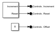
To create the virtual bus, the CounterSystem model uses a subsystem that contains Out Bus Element blocks. Each Out Bus Element block labeled Controls corresponds to an element of the bus.
Bus Interface Specification with Signal Attributes
In the subsystem of the CounterSystem model, the port named Controls both creates and defines the virtual bus.
To define the interface, the port named Controls specifies:
A bus element named
Incrementwith anint32data typeA bus element named
Resetwith abooleandata typeA bus element named
Offset
To view this specification, open the Property Inspector. Then, select an Out Bus Element block. For example, select the block labeled Controls.Increment.
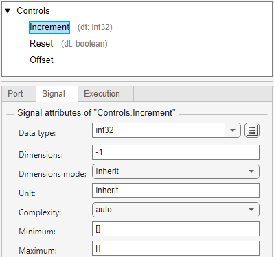
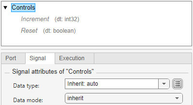
In the CounterAlgorithm model, the In Bus Element block labeled Controls receives the virtual bus.
To define the interface, the port named Controls specifies:
A bus element named
Incrementwith anint32data typeA bus element named
Resetwith abooleandata type
The port specifies a subset of the elements from the input bus. This subset represents only the elements that the referenced model uses. The referenced model does not use the bus element named Offset.
To view the specification, open the Property Inspector. Then, select the In Bus Element block labeled Controls.
View Usage of Interface Elements
To inspect the interface of a component, use the Component Interface View.
In the Simulink Toolstrip, on the Modeling tab, in the Design gallery, select Interface View.
Select a port on the component boundary.
Click Show usage.
To trace the usage of another element, in the Property Inspector, select the element.
Optionally, navigate through the hierarchy to view the usage of elements within other components.
Applications
To log and load simulation data for this model hierarchy, see Load Data to Represent Nonvirtual Bus Input from Model Hierarchy.
To log data only at specified time intervals for this model hierarchy, see Logging Intervals.
To explore big data as simulation input and output with this model hierarchy, see Working with Big Data.
To conceal the intellectual property of the model named
CounterAlgorithm, see Protected Model Capabilities.