Probe
Output signal attributes, including width, dimensionality, sample time, and complex signal flag
Libraries:
Simulink /
Signal Attributes
HDL Coder /
Signal Attributes
Description
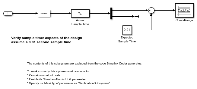
The Probe block outputs selected information about the signal on its input. The block can output the following attributes of the input signal: width, dimensionality, sample time, and a flag indicating whether the input is a complex-valued signal. The block has one input port. The number of output ports depends on the information that you select for probing, that is, signal dimensionality, sample time, and/or complex signal flag. Each probed value is output as a separate signal on a separate output port, with an independent data type control. During simulation, the block icon displays the probed data.
Examples
Ports
Input
Port_1 — Input signal
scalar | vector | matrix | N-D array
Input signal to probe, specified as a scalar, vector, matrix, or N-D array. The block accepts real or complex-valued signals of any built-in data type.
You can use an array of buses as an input signal to a Probe block. For details about defining and using an array of buses, see Group Nonvirtual Buses in Arrays of Buses.
Data Types: single
| double
| half
| int8
| int16
| int32
| int64
| uint8
| uint16
| uint32
| uint64
| string
| Boolean
| fixed point
| enumerated
| bus
Output
Port_1 (W) — Signal width
scalar
Width, or number of elements, in the input signal, specified as a
scalar. The width is also displayed on the block icon with the notation
W:
.
Dependencies
To enable this port, select Probe width.
Data Types: single
| double
| half
| int8
| int16
| int32
| int64
| uint8
| uint16
| uint32
| uint64
| fixed point
Port_2 (Ts) — Sample time
vector
Sample time of the input signal, as a two-element vector that
specifies the period and offset of the sample time, respectively. The
sample time is also displayed on the block icon with the notation
Ts:
. See Specify Sample Time
for more information.
Dependencies
To enable this port, select Probe sample time.
Data Types: single
| double
| half
| int8
| int16
| int32
| int64
| uint8
| uint16
| uint32
| uint64
| fixed point
Port_3 (C) — Signal complexity
scalar
Indication of input signal complexity:
When the input signal is complex, the block outputs
1
.When the input signal is real-valued, the block outputs
0
.
The indication of signal complexity is also displayed on
the block icon with the notation C:
.
Dependencies
To enable this port, select Detect complex signal.
Data Types: single
| double
| half
| int8
| int16
| int32
| int64
| uint8
| uint16
| uint32
| uint64
| fixed point
Port_4 (D) — Signal dimensions
scalar | vector
Dimensions of the input signal, output as a scalar or vector. The
signal dimensions are also displayed on the block icon with the notation
D:
.
Dependencies
To enable this port, select Probe signal dimensions.
Data Types: single
| double
| half
| int8
| int16
| int32
| int64
| uint8
| uint16
| uint32
| uint64
| fixed point
Parameters
Main
Probe width — Output width of the input signal
on
(default) | off
Select to output the width, or number of elements, of the probed signal.
Programmatic Use
Block Parameter:
ProbeWidth |
Type: character vector |
Values:
'off' | 'on' |
Default:
'on' |
Probe sample time — Output sample time of input signal
on
(default) | off
Select to output the sample time of the probed signal. The output is a two-element vector that specifies the period and offset of the sample time, respectively. See Specify Sample Time for more information.
Programmatic Use
Block Parameter:
ProbeSampleTime |
Type: character vector |
Values:
'off' | 'on' |
Default:
'on' |
Detect complex signal — Indicate the complexity of input signal
on
(default) | off
Select to output 1
if the probed signal is complex;
otherwise, 0
.
Programmatic Use
Block Parameter:
ProbeComplexSignal |
Type: character vector |
Values:
'off' | 'on' |
Default:
'on' |
Probe signal dimensions — Output dimensions of input signal
on
(default) | off
Select to output the dimensions of the probed signal.
Programmatic Use
Block Parameter:
ProbeSignalDimensions |
Type: character vector |
Values:
'off' | 'on' |
Default:
'on' |
Signal Attributes
Data type for width — Data type of signal width output
double
(default) | single
| int8
| uint8
| int16
| uint16
| int32
| uint32
| Same as input
Select the output data type for the signal width.
Programmatic Use
Block Parameter:
ProbeWidthDataType |
Type: character vector |
Values:
'double' | 'single' | 'int8' | 'uint8' | 'int16' |
'uint16' | 'int32' | 'uint32' | 'Same as
input' |
Default:
'double' |
Data type for sample time — Data type of sample time output
double
(default) | single
| int8
| uint8
| int16
| uint16
| int32
| uint32
| Same as input
Select the output data type for the sample time information.
Programmatic Use
Block Parameter:
ProbeSampleTimeDataType |
Type: character vector |
Values:
'double' | 'single' | 'int8' | 'uint8' | 'int16' |
'uint16' | 'int32' | 'uint32' | 'Same as
input' |
Default:
'double' |
Data type for signal complexity — Data type of complexity output
double
(default) | single
| int8
| uint8
| int16
| uint16
| int32
| uint32
| boolean
| Same as input
Select the output data type for the complexity information.
Programmatic Use
Block Parameter:
ProbeComplexityDataType |
Type: character vector |
Values:
'double' | 'single' | 'int8' | 'uint8' | 'int16' |
'uint16' | 'int32' | 'uint32' | 'Same as
input' |
Default:
'double' |
Data type for signal dimensions — Data type for signal dimension output
double
(default) | single
| int8
| uint8
| int16
| uint16
| int32
| uint32
| Same as input
Select the output data type for the signal dimension output.
Programmatic Use
Block Parameter:
ProbeDimensionsDataType |
Type: character vector |
Values:
'double' | 'single' | 'int8' | 'uint8' | 'int16' |
'uint16' | 'int32' | 'uint32' | 'Same as
input' |
Default:
'double' |
Block Characteristics
Data Types |
|
Direct Feedthrough |
|
Multidimensional Signals |
|
Variable-Size Signals |
|
Zero-Crossing Detection |
|
Extended Capabilities
C/C++ Code Generation
Generate C and C++ code using Simulink® Coder™.
HDL Code Generation
Generate VHDL, Verilog and SystemVerilog code for FPGA and ASIC designs using HDL Coder™.
HDL Coder™ provides additional configuration options that affect HDL implementation and synthesized logic.
This block has one default HDL architecture.
ConstrainedOutputPipeline | Number of registers to place at
the outputs by moving existing delays within your design. Distributed
pipelining does not redistribute these registers. The default is
|
OutputPipeline | Number of output pipeline stages
to insert in the generated code. Distributed pipelining and constrained
output pipelining can move these registers. The default is
|
This block supports code generation for complex signals.
Fixed-Point Conversion
Design and simulate fixed-point systems using Fixed-Point Designer™.
Version History
Introduced before R2006a
Comando de MATLAB
Ha hecho clic en un enlace que corresponde a este comando de MATLAB:
Ejecute el comando introduciéndolo en la ventana de comandos de MATLAB. Los navegadores web no admiten comandos de MATLAB.
Select a Web Site
Choose a web site to get translated content where available and see local events and offers. Based on your location, we recommend that you select: .
You can also select a web site from the following list:
How to Get Best Site Performance
Select the China site (in Chinese or English) for best site performance. Other MathWorks country sites are not optimized for visits from your location.
Americas
- América Latina (Español)
- Canada (English)
- United States (English)
Europe
- Belgium (English)
- Denmark (English)
- Deutschland (Deutsch)
- España (Español)
- Finland (English)
- France (Français)
- Ireland (English)
- Italia (Italiano)
- Luxembourg (English)
- Netherlands (English)
- Norway (English)
- Österreich (Deutsch)
- Portugal (English)
- Sweden (English)
- Switzerland
- United Kingdom (English)