Approaches to Control Active Variant Choice of a Variant Block Using Mask or Model Workspace
This example shows different approaches to control the active choice of inline variant and Variant Subsystem blocks from a mask or a model workspace. For more information on Variant blocks, see What Are Variants and When to Use Them.
Model
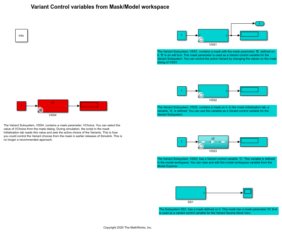
In this example, four Simulink® models are highlighted in green, and one model is highlighted in red. The models in green represent the recommended approaches to control the active choice of Variant blocks. These approaches let you limit the scope of the variant control variable, avoid name conflicts, and establish a clear ownership of the variable between Variant blocks. They also allow you to use the same names for variables in different scopes.
Limitations of Recommended Approaches
Work only if the Variant control mode parameter is set to
expressionand the Variant activation time parameter is set toupdate diagramorupdate diagram analyze all choices. When you useupdate diagram, Simulink does not analyze signal attributes of variant choices for consistency and generates code only for the active choice. When you useupdate diagram analyze all choices, Simulink analyzes signal attributes of active and inactive choices. However, it generates code only for the active choice.Do not support using
Simulink.VariantExpressionobjects orSimulink.Parameteras variant control variables.Do not support using model arguments variables as variant control variables.
The number of characters in the variant control variable must not exceed 40.
The variant control variable originating from a mask workspace must not start with
SLMASK.
Approach 1: Use Mask Parameter as a Variant Control Variable
This section explains how to control the active variant choice of Variant Subsystem blocks and inline variant blocks by using a mask parameter.
Control Active Choice of a Variant Subsystem Block using Mask Parameter
Consider the model with Variant Subsystem block VSS1. The VSS1 subsystem specifies two potential variants, x2 and x3. The control expression for x2 is B == 1 and for x3 is B == 2. The variable B is a mask parameter. To view the properties of B:
1. Right-click the VSS1 subsystem.
2. Select Mask > Edit Mask. In the Parameters & Dialog pane, under Parameters, the Prompt column specifies the label of the parameter on the mask dialog box, and the Name column specifies the name of the mask parameter. In this example, Prompt is specified as Enter the choice, and Name is specified as B.
3. To open the mask dialog box, double-click the VSS1 subsystem. During simulation, the index of the value that you specify here is mapped to the underlying variable B, which is then used to evaluate the variant condition expressions associated with the block. In this example, the default value of Enter the choice is 2. When you simulate this model, the variant condition B == 2 evaluates to true. The x2 subsystem becomes inactive, and the x3 subsystem becomes active.
4. To modify the active choice, specify the value as 1 in the mask dialog box, then simulate the model again. During simulation, the value of the B is set to 1 which in turn evaluates the Variant condition, B == 1 to true. The x2 subsystem becomes active, and the x3 subsystem becomes inactive.

Control Active Choice of Inline Variant Blocks using Mask Parameter
Consider the model with masked Subsystem block SS1. The SS1 subsystem has a mask parameter VC that is used as a variant control variable in the underlying Variant Source block Vsrc. The first input port is associated with the control expression VC == 1 and the second input port is associated with the control expression VC == 2. To view the properties of VC:
1. Right-click the SS1 subsystem.
2. Select Edit Mask. In the Parameters & Dialog pane, under Parameters, the Prompt column specifies the label of the parameter on the mask dialog box, and the Name column specifies the name of the mask parameter. In this example, Prompt is specified as Choose the signal, and Name is specified as VC.
3. To open the mask dialog box, double-click the SS1 subsystem. During simulation, the index of the value that you select here is mapped to the underlying variable VC, which is then used to evaluate the variant condition expressions associated with the Vsrc block. In this example, the default value of Choose the signal is Sine Wave. When you simulate this model, the index of the Sine Wave, 2, is mapped to VC. The variant condition VC == 2 evaluates to true. As a result, the first input port of the Vsrc block that is associated with VC == 1 becomes inactive and the second input port that is associated with VC == 2 becomes active.
4. To modify the active choice, select the value as Constant in the mask dialog box, then simulate the model again. During simulation, the value of the VC is set to 1 which in turn evaluates the variant condition, VC == 1 to true. The first input port of the Vsrc block becomes active and the second input port becomes inactive.

Approach 2: Use Mask Initialization Variable as a Variant Control Variable
This section explains how to control the active variant choice of Variant Subsystem blocks using a mask initialization variable. You can follow this approach to control the active variant choice of inline variant blocks as well.
Consider the model with Variant Subsystem block VSS2. 1. In the VSS2 subsystem, the control expression for x2 is A == 1 and for x3 is A == 2. The variable A used in the control expression is a regular MATLAB® variable that is defined using a function in the Code tab of the mask workspace. To view the properties of A:
a. Right-click the VSS2 subsystem.
b. Select Mask > Edit Mask. In the Code tab, under Initialization code section, set the value of A to 1 using the function initialization().
During simulation, this value is used to evaluate the variant condition expressions associated with the block. When you simulate this model, the variant condition A == 1 evaluates to true. The x2 subsystem becomes active, and the x3 subsystem becomes inactive.
3. To modify the active choice, specify the value of A as 2 in the function initialization() in the Code tab, then simulate the model again. During simulation, A == 2 evaluates to true. The x2 subsystem becomes active, and the x3 subsystem becomes inactive.

Approach 3: Use Model Workspace Variable as a Variant Control Variable in a Variant Subsystem Block
This section explains how to control the active variant choice of Variant Subsystem blocks using a model workspace variable. You can follow this approach to control the active variant choice of inline variant blocks as well.
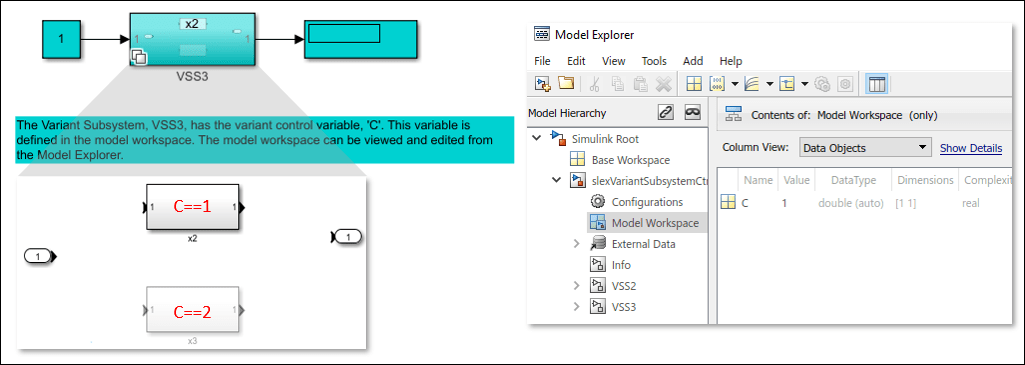
Consider the model with Variant Subsystem block VSS3. 1. In the VSS3 subsystem, the control expression for x2 is C == 1 and for x3 is C == 2. The variable C used in the condition expression is a regular MATLAB® variable that is defined in the model workspace. To view the properties of C:
a. On the Modeling tab, click Model Explorer.
b. In the Model Hierarchy pane, click Model Workspace. The value of C is set to 1.
During simulation, this value is used to evaluate the variant condition expressions associated with the block. When you simulate this model, the variant condition C == 1 evaluates to true. The x2 subsystem becomes active, and the x3 subsystem becomes inactive. To modify the active choice, specify the value of C as 2, then simulate the model again. During simulation, the Variant condition C == 2 evaluates to true. The x2 subsystem becomes active, and the x3 subsystem becomes inactive.
Approach 4: Use Mask Initialization Script to Control Active Variant Choices of a Variant Subsystem Block
This approach is not recommended for controlling the active variant choice of Variant Subsystems. However, if the Variant control mode of the subsystem is set to Label mode, you can follow this approach. For more information, see Mask a Variant Subsystem.
See Also
Control Active Choice of Locked Custom Library Variant Subsystem Using Mask Parameter
You can also select a web site from the following list:
Americas
- América Latina (Español)
- Canada (English)
- United States (English)
Europe
- Belgium (English)
- Denmark (English)
- Deutschland (Deutsch)
- España (Español)
- Finland (English)
- France (Français)
- Ireland (English)
- Italia (Italiano)
- Luxembourg (English)
- Netherlands (English)
- Norway (English)
- Österreich (Deutsch)
- Portugal (English)
- Sweden (English)
- Switzerland
- United Kingdom (English)