Design Custom Knobs
This example shows how to use the customizable Knob block to design three knobs that look like controls in real systems:
The cabin temperature knob of a passenger car
The volume knob of a radio
A stove knob

Each knob consists of a stationary component, the mounting, and a movable component, which is the handle that you turn to set the value.
The blocks in the model use PNG images to define the shapes of these components. You can find all images used to create the knobs in the example directory.
Design Cabin Temperature Knob of Passenger Car
To design the cabin temperature knob, add a customizable Knob block to the model using the Simulink® quick insert menu:
To open the quick insert menu, double-click in the canvas.
To search for the customizable Knob block, type
Knob.Select the search result with the library path
Simulink/Dashboard/Customizable Blocks.
To modify the design of the Knob block, enter design mode:
In the model canvas, select the Knob block.
In the Simulink Toolstrip, click the Knob tab.
On the Knob tab, click Edit. A toolbar appears above the Knob block.
To open the Property Inspector, in the toolbar, click Open Design Tab. In design mode, the Design tab of the Property Inspector is active.
You can design a customizable knob using the toolbar or using the Design tab of the Property Inspector. This example uses both.

Add the background image for the cabin temperature knob:
In the toolbar, click the Replace Background Image button.
In the
CustomKnobImagesfolder, select thecabin-temp-knob-background.pngfile.

Add the handle image for the cabin temperature knob:
In the toolbar, click the Replace Needle Image button.
In the
CustomKnobImagesfolder, select thecabin-temp-knob-handle.pngfile.

Adjust the endpoints of the scale:
Adjust the start offset angle. On the tick mark that constitutes the left end of the scale, click and drag the blue marker so that the tick mark aligns with the blue end of the color bar on the background image. By default, the blue markers snap to angles located at 15 degree intervals. To avoid snapping to these angles, press Shift while dragging the marker.
Adjust the scale angle. On the tick mark that constitutes the right end of the scale, click and drag the blue marker so that the tick mark lines up with the red end of the color bar on the background image.

For the next two steps, return to the Property Inspector. To open the Design Tab of the Property Inspector, click Open Design Tab in the toolbar.

Hide the scale:
On the Design tab, select the Scale component.
In the Ticks section, clear Show Ticks.
In the Ticks section, clear Show Span Line.
In the Labels section, clear Show Labels.

The customizable Knob block has a value bar: a circular arc whose length serves as a visual representation of the value to which the knob is set. To see the value bar:
On the Design tab, select the Value Bar component.
In Value Preview, move the Value slider and see how the value bar changes as the handle of the knob moves.

The cabin temperature knob does not use the value bar. To hide the value bar, in the toolbar, move the Set Opacity slider to zero.

When you finish adjusting the design for the cabin temperature knob, to exit design mode, on the Design tab of the Property Inspector, click Edit.
You can use the finished cabin temperature knob to control a parameter. In the model, a Constant block represents the cabin temperature of a passenger car, and the cabin temperature knob controls the value of the constant.

Connect the Knob block to the Value parameter of the Constant block:
Select the Knob block.
Click the Connect button that appears above the block.
Select the Constant block named
Const1.Select the
Const1:Valueoption in the table that appears below the selected signal.Click the
Xin the upper right corner of the Simulink window.
To use the cabin temperature knob:
Simulate the model. This model uses simulation pacing to slow model execution so you can interact with the model during simulation. For more information about simulation pacing, see Simulation Pacing Options.
Click and drag the Knob block handle to change its value during simulation.
See the effect on the cabin temperature in the Dashboard Scope block.
Design Volume Knob of Radio
To design the radio volume knob, add a customizable Knob block to the model.
If the Property Inspector is not open to the Design tab with the Edit button pressed:
In the model canvas, select the Knob block.
In the Simulink Toolstrip, click the Knob tab.
On the Knob tab, click Edit. A toolbar appears above the Knob block.
To open the Property Inspector, in the toolbar, click Open Design Tab.

Add the background image for the volume knob:
In the Property Inspector, on the Design tab, select the Background Image component.
In the Select Image section, click the plus button.
In the
CustomKnobImagesfolder, select theradio-knob-background.pngfile.
Add the handle image for the volume knob:
On the Design tab, select the Handle component.
In the Select Image section, click the plus button.
In the
CustomKnobImagesfolder, select theradio-knob-handle.pngfile.

Change the color of the value bar:
On the Design tab, select the Value Bar component.
In the Value Preview section, move the Value slider to preview the value bar.
In the Value Bar section, set the Color to turquoise.
The inner and outer radius of the value bar are the same as the inner and outer radius of the tick marks on the knob scale. Change the inner and outer radius of the value bar such that the bar covers the dark gray swoosh on the background image:
On the Design tab, select the Scale component.
In the Range section, adjust the Inner Radius slider to make the inner radius of the value bar smaller than that of the gray swoosh. The example uses an Inner Radius value of 0.55.
In the Range section, adjust the Outer Radius slider to make the outer radius of the value bar larger than that of the gray swoosh. The example uses an Outer Radius value of 0.78.

The scale is hard to read because the light yellow color of the tick marks and labels blends into the white background, and because the labels are half on and half off of the knob background. To make the scale readable so that you can adjust the arc length of the scale, set the color of the scale to black:
In the Ticks section, set the Color to black.
In the Labels section, set the Color to black.
In the Labels section, adjust the Label Radius slider to move the scale labels outside of the outer radius of the knob. The example uses a Label Radius value of 0.92.

Adjust the arc length of the scale:
In the Range section, set the Start Angle to 270 degrees to place the start point of the scale on the positive vertical axis. The angle is measured clockwise from the horizontal axis that bisects the right half of the knob.
In the Range section, set Arc to 90 degrees to place the end point of the scale one quarter of a full knob revolution from the start point.

Hide the scale:
In the Ticks section, clear Show Ticks.
In the Ticks section, clear Show Span Line.
In the Labels section, clear Show Labels.
Add the foreground image for the volume knob:
On the Design tab, select the Foreground Image component.
In the Select Image section, click the plus button.
In the
CustomKnobImagesfolder, select theradio-knob-foreground.pngfile.

When you finish adjusting the design for the volume knob, to exit design mode, on the Design tab, click Edit.
You can use the finished volume knob to control a parameter. In the model, a Sine Wave block represents a radio signal, and the volume knob controls the amplitude of the sine wave.

Connect the Knob block to the Amplitude parameter of the Sine Wave block:
Select the Knob block.
Click the Connect button that appears above the block.
Select the Sine Wave block.
Select the
Sine Wave:Amplitudeoption in the table that appears below the selected signal.Click the
Xin the upper right corner of the Simulink window.
To use the volume knob:
Simulate the model. This model uses simulation pacing to slow model execution so you can interact with the model during simulation. For more information about simulation pacing, see Simulation Pacing Options.
Click and drag the Knob block handle to change its value during simulation.
See the effect on the radio signal in the Dashboard Scope block.
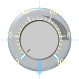
Design a Stove Knob
To design the stove knob, add a customizable Knob block to the model.
If the Property Inspector is not open to the Design tab with the Edit button pressed:
In the model canvas, select the Knob block.
In the Simulink Toolstrip, click the Knob tab.
On the Knob tab, click Edit. A toolbar appears above the Knob block.
To open the Property Inspector, in the toolbar, click Open Design Tab.
Add the background image for the stove knob:
In the Property Inspector, on the Design tab, select the Background Image component.
In the Select Image section, click the plus button.
In the
CustomKnobImagesfolder, select thestove-knob-background.pngfile.

Add the handle image for the stove knob:
On the Design tab, select the Handle component.
In the Select Image section, click the plus button.
In the
CustomKnobImagesfolder, select thestove-knob-handle.pngfile.

To edit the scale, make it readable by changing its color:
On the Design tab, select the Scale component.
In the Ticks section, set the Color to black.
In the Labels section, set the Color to black.
The range of the stove knob scale labels spans from 0 to 10. The minimum of the range is the default value of the Knob block. In the Range section, set the Maximum to 10.
The arc length of the stove knob scale is the default value, 270 degrees. The start angle of the scale is 315 degrees, measured clockwise from the horizontal axis that bisects the right half of the knob. In the Range section, set the Start Angle to 315.
Adjust the span line, tick marks, and labels of the scale so that they fit on the knob:
In the Range section, adjust the radius of the span line of the scale by moving the Outer Radius slider. Bring the span line close to the outer radius of the knob handle. The example uses an Outer Radius value of 0.55.
In the Range section, adjust the width of the tick marks of the scale by moving the Inner Radius slider. To keep the span line at the inner radius of the scale, set an Inner Radius value larger than that of the Outer Radius. Set the Inner Radius value such that the tick marks take up about a third of the radial distance between the outer radius of the knob handle, and the outer radius of the knob. The example uses an Inner Radius value of 0.63.
In the toolstrip, on the Format tab, under Font and Paragraph, set the font size of the labels to 10.
On the Design tab, select the Scale component again.
In the Labels section, adjust the Label Radius slider to move the scale labels such that they are between the outer radius of the tick marks and the outer radius of the knob. The example uses a Label Radius value of 0.7.

Hide the value bar:
On the Design tab, select the Value Bar component.
In the Value Bar section, set the Opacity to zero.
When you finish adjusting the design for the stove knob, to exit design mode, on the Design tab, click Edit.
You can use the finished stove knob to control a parameter. In the model, a Constant block represents the heat setting of a stove, and the stove knob controls the value of the constant. The product of the heat setting and a gain represent the resulting stove temperature.

Connect the Knob block to the Value parameter of the Constant block:
Select the Knob block.
Click the Connect button that appears above the block.
Select the Constant block named
Const2.Select the
Const2:Valueoption in the table that appears below the selected signal.Click the
Xin the upper right corner of the Simulink window.
To use the stove knob:
Simulate the model. This model uses simulation pacing to slow model execution so you can interact with the model during simulation. For more information about simulation pacing, see Simulation Pacing Options.
Click and drag the Knob block handle to change its value during simulation.
See the effect on the stove temperature in the Dashboard Scope block.