Design Custom Rotary Switches
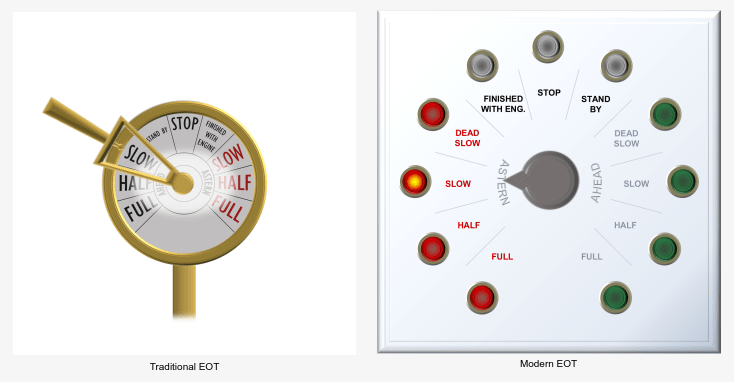
An engine order telegraph (EOT) is a device used on ships to communicate the commanded speed and direction of travel from the bridge to the engine room. Personnel on the bridge use the EOT to control the velocity of the ship from outside the engine room.
This example shows how to use the customizable Rotary Switch block to design two EOTs that look like controls in real systems:
A mechanical EOT
An electronic EOT
Each switch consists of a stationary component and a movable component. The stationary component is the mounting, and the movable component is the handle that you turn to set the value of the parameter that the switch controls.
The blocks in the model use PNG images to define the shapes of these components. You can find all images used to create the switches in the example directory.
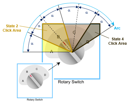
Each switch has multiple states. A state pairs a State Value with a customizable State Label, a handle orientation, and a click area.
You can activate a state by clicking its click area or by dragging the handle and releasing it over the click area. When you activate the state, the State Value is assigned to the Simulink® block diagram element to which the switch block is connected.
You can specify the arc angle the handle traverses when it moves from the first state to the last state. The state labels are evenly spaced over the arc length. The edges of the click areas bisect the angular distance between labels.
Design Mechanical EOT
To design the mechanical EOT, add a customizable Rotary Switch block to the model using the Simulink quick insert menu:
To open the quick insert menu, double-click in the canvas.
To search for the customizable Rotary Switch block, type
Rotary Switch.Select the search result with the library path
Simulink/Dashboard/Customizable Blocks.
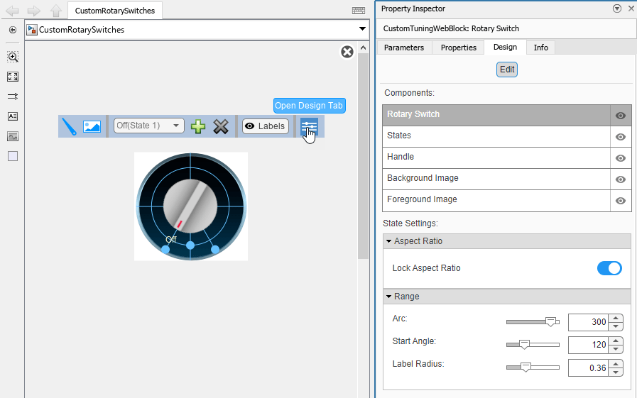
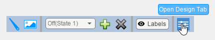
To modify the design of the Rotary Switch block, enter design mode:
In the model canvas, select the Rotary Switch block.
In the Simulink Toolstrip, click the Switch tab.
On the Switch tab, click Edit. A toolbar appears above the Rotary Switch block.
To open the Property Inspector, in the toolbar, click Open Design Tab. In design mode, the Design tab of the Property Inspector is active.
You can design a custom rotary switch using the toolbar or using the Design tab of the Property Inspector. This example uses both.
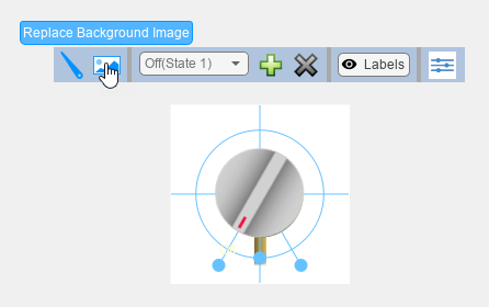
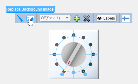
Add the background image for the mechanical EOT:
In the toolbar, click Replace Background Image.
In the
CustomRotarySwitchImagesfolder, select theeot-1-background.pngfile.
Resize the block to make the text on the EOT in the background image large enough to read:
Make the full background image visible by deleting the handle image. On the Design tab of the Property Inspector, click the Handle component. Then, in the Handle component, underneath the handle image, click the
Xbutton.To resize the block, exit design mode. In the Property Editor, on the Design tab, click Edit.
Click and drag one of the corners of the block outwards until the text on the background image is large enough to read.
To continue modifying the design of the Rotary Switch block, enter design mode again.
Add the handle image for the mechanical EOT:
On the Design tab, select the Handle component.
In the Select Image section, click the plus button.
In the
CustomRotarySwitchImagesfolder, select theeot-1-handle.pngfile. Note that the handle in the PNG file points to the right.
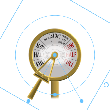
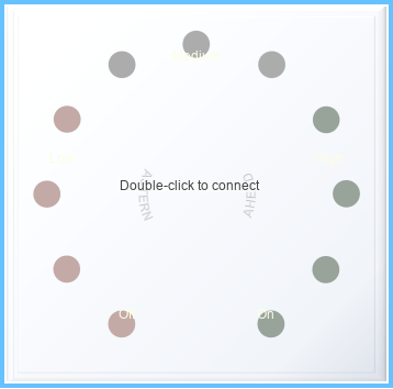
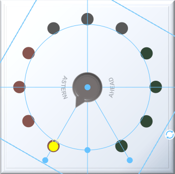
The states of the mechanical EOT Rotary Switch block have this layout:
The background image shows nine labels spaced at 30 degree intervals. Each label corresponds to an EOT state. The mechanical EOT Rotary Switch block is split into nine corresponding state sections, shown in yellow.
State 1is theFULLahead command on the background image.The Arc is the arc length the rotary switch handle traverses when it moves from the first state to the last state. For the mechanical EOT Rotary Switch block, the arc length spans from the middle of the
FULLahead section to the middle of theFULLastern section, which is an angular distance of 240 degrees.The Start Angle is the angular location of the end of the arc length that is in
State 1, measured clockwise from the positive horizontal axis pointing right. For the mechanical EOT Rotary Switch block, the Start Angle is the angular location of the middle of theFULLahead section relative to the positive horizontal axis, which is 150 degrees.Since the background image already has the labels for each section marked, the Rotary Switch block state labels are hidden.

Implement the state layout:
In the Property Inspector, on the Design tab, select the Rotary Switch component.
In the Range section, set Arc to
240degrees.In the Range section, set Start Angle to
150degrees.To hide the Rotary Switch blocks state labels, make the label radius large enough to move the labels out of view. In the Range section, set Label Radius to
1.
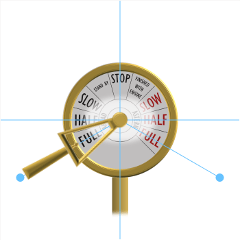
The Rotary Switch block for the mechanical EOT has nine states:
In State 1, the bridge orders the engine to travel ahead at the full engine speed. The Rotary Switch block has a State Value of
100and the State LabelFull Speed, Ahead.In State 2, the bridge orders the engine to travel ahead at 50 percent of the full engine speed. The Rotary Switch block has a State Value of
50and the State LabelHalf Speed, Ahead.In State 3, the bridge orders the engine to travel ahead at 25 percent of the full engine speed. The Rotary Switch block has a State Value of
25and the State LabelSlow Speed, Ahead.In State 4, the bridge orders the engine to stand by. The Rotary Switch block has a State Value of
1and the State LabelStand By.In State 5, the bridge orders the engine to stop, and the engine speed is 0. The Rotary Switch block has a State Value of
0and the State LabelStop.In State 6, the bridge is finished with the main engine. The Rotary Switch block has a State Value of
-1and the State LabelFinished with Engine.In State 7, the bridge orders the engine to travel astern at 25 percent of the full engine speed. The Rotary Switch block has a State Value of
-25and the State LabelSlow Speed, Astern.In State 8, the bridge orders the engine to travel astern at 50 percent of the full engine speed. The Rotary Switch block has a State Value of
-50and the State LabelHalf Speed, Astern.In State 9, the bridge orders the engine to travel astern at the full engine speed. The Rotary Switch block has a State Value of
-100and the State LabelFull Speed, Astern.
In the Property Inspector, on the Design tab, for each state:
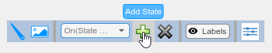
In the States component, in the Select State section, expand the drop-down list. If the state number is listed, select the corresponding state. If not, click the plus button to add a new state.
In the Value section, enter the
State Value.To make the state identifiable in the Select State section drop-down list, in the Label section, enter the
State Labelin the Text field. When you click out of the Text field, the label appears in the Select State section drop-down list.
Note that the handle orientation for a given state not be correct until all nine states have been added because the Rotary Switch block does not recognize the labels on the background image. The Rotary Switch block spaces state labels at equal angular intervals, so the angular locations to which the handle snaps depend on the number of states. When there are nine states, the angular locations of the Rotary Switch block state labels coincide with the angular locations of the labels on the background image, and the handle takes on the correct orientation for all states.
When you finish adjusting the design for the mechanical EOT, to exit design mode, in the Property Inspector, on the Design tab, click Edit.
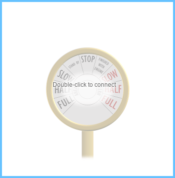
You can use the finished EOT to control a parameter. In the model, a Constant block represents the EOT signal that is sent to the engine room. The Rotary Switch block controls the value of the constant.
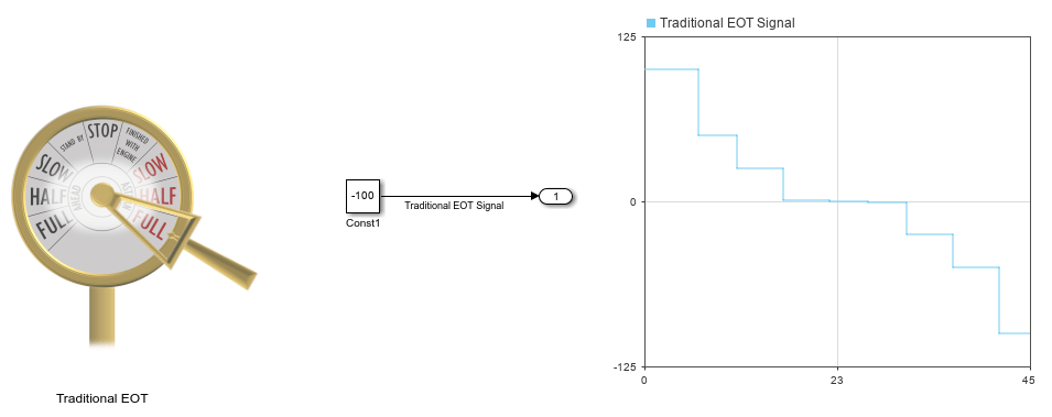
Connect the Rotary Switch block to the Value parameter of the Constant block:
Select the Rotary Switch block.
Click the Connect button that appears above the block.
Select the Constant block named
Const1.In the table that appears below the selected signal, select the
Const1:Value.Click the
Xin the upper right corner of the Simulink window.
To use the mechanical EOT:
Simulate the model. This model uses simulation pacing to slow model execution so you can interact with the model during simulation. For more information about simulation pacing, see Simulation Pacing Options.
During simulation, click and drag the handle. To change the
State Valueof the Rotary Switch block, release the handle over any of the labels on the background image.See the effect on the EOT signal in the Dashboard Scope block.
Design Electronic EOT
To design the electronic EOT, add a customizable Rotary Switch block to the model.
If the Property Inspector is not open to the Design tab with the Edit button pressed:
In the model canvas, select the Rotary Switch block.
In the Simulink Toolstrip, click the Switch tab.
On the Switch tab, click Edit. A toolbar appears above the Rotary Switch block.
To open the Property Inspector, in the toolbar, click Open Design Tab.
Add the background image for the electronic EOT:
In the toolbar, click Replace Background Image.
In the
CustomRotarySwitchImagesfolder, select theeot-2-background.pngfile.
Resize the block to make the text on the EOT in the background image large enough to read:
Make the full background image visible by deleting the handle image. On the Design tab of the Property Inspector, click the Handle component. Then, in the Handle component, underneath the handle image, click the
Xbutton.To resize the block, exit design mode. In the Property Editor, on the Design tab, click Edit.
Click and drag one of the corners of the block outwards until the text on the background image is large enough to read.
To continue modifying the design of the Rotary Switch block, enter design mode again.
Add the handle image for the electronic EOT:
On the Design tab, select the Handle component.
In the Select Image section, click the plus button.
In the
CustomRotarySwitchImagesfolder, select theeot-2-handle.pngfile. Note that the handle in the PNG file points to the right.In the Size section, set the Width and Height to
1.
The states of the electronic EOT Rotary Switch block have this layout:
The background image shows eleven labels spaced at 30 degree intervals. Each label corresponds to an EOT state. The electronic EOT Rotary Switch block is split into eleven corresponding state sections, shown in yellow.
State 1is theFULLastern command on the background image.The Arc is the arc length the rotary switch handle traverses when it moves from the first state to the last state. For the electronic EOT Rotary Switch block, the arc length spans from the middle of the
FULLahead section to the middle of theFULLastern section, which is an angular distance of 300 degrees.The Start Angle is the angular location of the end of the arc length that is in
State 1, measured clockwise from the positive horizontal axis pointing right. For the electronic EOT Rotary Switch block, the Start Angle is the angular location of the middle of theFULLahead section relative to the positive horizontal axis, which is 120 degrees.Since the background image already has the labels for each section marked, the Rotary Switch block state labels are hidden.
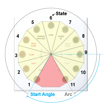
Arc is 300 degrees by default. Start Angle is 120 degrees by default.
To hide the Rotary Switch blocks state labels, make the label radius large enough to move the labels out of view:
In the Property Inspector, on the Design tab, select the Rotary Switch component.
In the Range section, set Label Radius to
1.
The Rotary Switch block for the mechanical EOT has eleven states:
In State 1, the bridge orders the engine to travel astern at the full engine speed. The Rotary Switch block has a State Value of
-100and the State LabelFull Speed, Astern.In State 2, the bridge orders the engine to travel astern at 50 percent of the full engine speed. The Rotary Switch block has a State Value of
-50and the State LabelHalf Speed, Astern.In State 3, the bridge orders the engine to travel astern at 25 percent of the full engine speed. The Rotary Switch block has a State Value of
-25and the State LabelSlow Speed, Astern.In State 4, the bridge orders the engine to travel astern at 12.5 percent of the full engine speed. The Rotary Switch block has a State Value of
-12.5and the State LabelDead Slow Speed, Astern.In State 5, the bridge is finished with the main engine. The Rotary Switch block has a State Value of
-1and the State LabelFinished with Engine.In State 6, the bridge orders the engine to stop, and the engine speed is 0. The Rotary Switch block has a State Value of
0and the State LabelStop.In State 7, the bridge orders the engine to stand by. The Rotary Switch block has a State Value of
1and the State LabelStand By.In State 8, the bridge orders the engine to travel ahead at 12.5 percent of the full engine speed. The Rotary Switch block has a State Value of
12.5and the State LabelDead Slow Speed, Ahead.In State 9, the bridge orders the engine to travel ahead at 25 percent of the full engine speed. The Rotary Switch block has a State Value of
25and the State LabelSlow Speed, Ahead.In State 10, the bridge orders the engine to travel ahead at 50 percent of the full engine speed. The Rotary Switch block has a State Value of
50and the State LabelHalf Speed, Ahead.In State 11, the bridge orders the engine to travel ahead at the full engine speed. The Rotary Switch block has a State Value of
100and the State LabelFull Speed, Ahead.
In the Property Inspector, on the Design tab, for each state:
In the States component, in the Select State section, expand the drop-down list. If the state number is listed, select the corresponding state. If not, click the plus button to add a new state.
In the Value section, enter the
State Value.To make the state identifiable in the Select State section drop-down list, in the Label section, enter the
State Labelin the Text field. When you click out of the Text field, the label appears in the Select State section drop-down list.
Note that the handle orientation for a given state not be correct until all eleven states have been added because the Rotary Switch block does not recognize the labels on the background image. The Rotary Switch block spaces state labels at equal angular intervals, so the angular locations to which the handle snaps depend on the number of states. When there are eleven states, the angular locations of the Rotary Switch block state labels coincide with the angular locations of the labels on the background image, and the handle takes on the correct orientation for all states.
Add the foreground image for the electronic EOT:
On the Design tab, select the Foreground Image component.
In the Select Image section, click the plus button.
In the
CustomRotarySwitchImagesfolder, select theeot-2-foreground.pngfile.

When you finish adjusting the design for the electronic EOT, to exit design mode, in the Property Inspector, on the Design tab, click Edit.
Use the finished EOT to control a parameter. In the model, a Constant block represents the EOT signal that is sent to the engine room, and the Rotary Switch block controls the value of the constant.

Connect the Rotary Switch block to the Value parameter of the Constant block:
Select the Rotary Switch block.
Click the Connect button that appears above the block.
Select the Constant block named
Const2.In the table that appears below the selected signal, select
Const2:Value.Click the
Xin the upper right corner of the Simulink window.
To use the electronic EOT:
Simulate the model. This model uses simulation pacing to slow model execution so you can interact with the model during simulation. For more information about simulation pacing, see Simulation Pacing Options.
During simulation, click and drag the handle. To change the
State Valueof the Rotary Switch block, release the handle over any of the labels on the background image.See the effect on the EOT signal in the Dashboard Scope block.