Frequency-Response Based Tuning
Frequency Response Based PID Tuner simulates the model to estimate the plant frequency responses at a few frequencies near the control bandwidth. It then uses the estimated frequency response to tune the gains in your PID Controller. This tuner is a useful alternative when PID Tuner cannot linearize the plant at the operating point you want to use for tuning.
Frequency Response Based PID Tuner can tune the P, I, D, and N parameters in PID Controller and PID Controller (2DOF) blocks in both continuous time and discrete time. For PID Controller (2DOF) blocks, the tuner does not tune the setpoint weights b and c.
How Frequency Response Based PID Tuner Works
Like the interactive PID Tuner, the Frequency Response Based PID Tuner considers the plant to be all blocks in the loop between the PID Controller block output and input. The Frequency Response Based PID Tuner performs a perturbation experiment to estimate the open-loop frequency response of the plant. To do so, the tuner performs the following steps:
Breaks the feedback loop at the controller output and simulates the model, applying perturbation signals to the plant. The perturbations include sinusoidal signals at frequencies [1/3,1,3,10]ωc , where ωc is the target bandwidth you specify for tuning. If the plant is asymptotically stable, the applied signal also includes a step perturbation.
Measures the response to the perturbation at the controller input.
Uses the resulting data to estimate the plant frequency response at the four frequencies. For asymptotically stable plants, the tuner also uses the response to the step perturbation to estimate the plant DC gain.
Uses the estimated frequency response to compute PID gains that balance performance and robustness.
If your model includes disturbances, the tuner can run two simulations: a simulation without perturbation to get a baseline response, and a simulation with the perturbations applied to the plant. The tuner then uses the difference between the two responses to remove the effects of disturbances in the model. In this case, the estimated frequency response used for tuning is based on this disturbance-free response.
Open Frequency Response Based PID Tuner
To open the Frequency Response Based PID Tuner, in the PID
Controller block dialog box, in the Select Tuning Method
drop-down list, select Frequency Response Based.
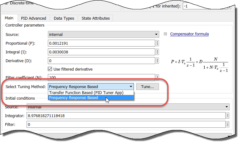
Click Tune. The Frequency Response Based PID Tuner opens. The tuner reads some parameters from the PID Controller block. These parameters include:
Controller type (such as PI, PD, or PID)
Controller form (parallel or ideal)
Controller time domain (continuous-time or discrete-time)
Controller sample time
In the Frequency Response Based PID Tuner, You configure the settings for the estimation experiment and the tuning goals.
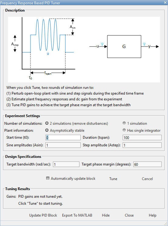
Configure Experiment Settings
In the Experiment Settings section, you specify parameters that control the frequency-response estimation experiment. For more details about these settings, click Help.
Specify whether to run two simulations (default) or one. If your model includes disturbances that can affect the result of the frequency-response estimation experiment, select 2 simulations (remove disturbances). With this option selected, the tuner runs a baseline simulation and subtracts the resulting frequency response from the perturbed simulation to remove the effects of disturbances. If your model does not include any such disturbances, skip the baseline simulation by selecting 1 simulation.
Specify whether the plant is asymptotically stable or has a single integrator. If the plant is asymptotically stable, the estimation experiment includes an estimation of the plant DC gain. The Frequency Response Based PID Tuner performs this estimation by injecting a step signal into the plant.
Caution
Do not use the Frequency Response Based PID Tuner with an unstable plant or a plant containing multiple integrators.
Specify the start time of the experiment in the Start time (t0) field. Start the experiment when the plant is at the desired equilibrium operating point. For instance, if you know that your simulation must run to 10 s for the plant to reach such an operating point, specify a start time of 10.
Specify the experiment duration in the Duration (tspan) field. Let the experiment run long enough for the frequency-response estimation algorithm to collect sufficient data for a good estimate at all frequencies it probes. A conservative estimate for the experiment duration is 100/ωc, where ωc is the target bandwidth for tuning that you specify.
Note
Frequency Response Based PID Tuner rounds up the Start time (t0) and Duration (tspan) to the nearest multiple of controller sample time.
Specify the perturbation amplitudes. During the tuning experiment, the Frequency Response Based PID Tuner injects a sinusoidal signal into the plant at four frequencies, [1/3,1,3,10]ωc . Use the Sine amplitudes (Asin) field to specify the amplitudes of these injected signals. You can provide a scalar value to inject the same amplitude at each frequency, or a vector of length 4 to specify different amplitudes for each.
In a typical plant with typical target bandwidth, the magnitudes of the plant responses at the experiment frequencies do not vary widely. In such cases, you can use a scalar value to apply the same magnitude perturbation at all frequencies. However, if you know that the response decays sharply over the frequency range, consider decreasing the amplitude of the lower-frequency inputs and increasing the amplitude of the higher-frequency inputs. It is numerically better for the estimation experiment when all the plant responses have comparable magnitudes.
The perturbation amplitudes must be:
Large enough that the perturbation overcomes any deadband in the plant actuator and generates a response above the noise level
Small enough to keep the plant running within the approximately linear region near the nominal operating point, and to avoid saturating the plant input or output
In the experiment, the sinusoidal signals are superimposed (with the step perturbation, if any, in the case of open-loop tuning). Thus, the perturbation can be at least as large as the sum of all amplitudes. Therefore, to obtain appropriate values for the amplitudes, consider:
Actuator limits. Make sure that the largest possible perturbation is within the range of your plant actuator. Saturating the actuator can introduce errors into the estimated frequency response.
How much the plant response changes in response to a given actuator input at the nominal operating point for tuning. For instance, suppose that you are tuning a PID controller used in engine-speed control. You have determined that at frequencies around the target bandwidth, a 1° change in throttle angle causes a change of about 200 rpm in the engine speed. Suppose further that to preserve linear performance the speed must not deviate by more than 100 rpm from the nominal operating point. In this case, choose amplitudes to ensure that the perturbation signal is no greater than 0.5 (assuming that value is within actuator limits).
If your plant is asymptotically stable, specify amplitude of the step perturbation in the Step amplitudes (Astep) field. The considerations for choosing a step amplitude are the same as the considerations for specifying the step amplitudes.
Configure Design Goals
In the Design Specifications section of the dialog box, you specify your goals for PID tuning.
Specify the target bandwidth in the Target bandwidth (rad/sec) field. The target bandwidth is the target value for the 0-dB gain crossover frequency of the tuned open-loop response CP, where P is the plant response, and C is the controller response. This crossover frequency roughly sets the control bandwidth. For a desired rise-time τ, a good guess for the target bandwidth is 2/τ.
In the Target phase margin (degrees) field, specify a target minimum phase margin for the tuned open-loop response at the crossover frequency. The target phase margin reflects desired robustness of the tuned system. Typically, choose a value in the range of about 45°– 60°. In general, higher phase margin improves overshoot, but can limit response speed. The default value, 60°, tends to balance performance and robustness, yielding about 5-10% overshoot, depending on the characteristics of your plant.
For more details about these settings, click Help.
Tune and Validate Controller Gains
Click Tune to initiate the frequency-response estimation experiment. While the estimation experiment is running, the tuner:
Closes the open PID Controller block.
Clears any previous tuning results displayed in the tuner dialog box.
Replaces the PID Controller block in your model with an unnamed subsystem.
Note
When the estimation experiment is completed or canceled, the tuner restores the PID Controller block. This process might result in some displacement of signal wires on the model canvas, and puts your Simulink® model in a state with unsaved changes.
When the estimation experiment ends, the tuner computes new PID gains and displays them in the Tuning Results section of the dialog box. (For more information about the tuning results, click Help.)
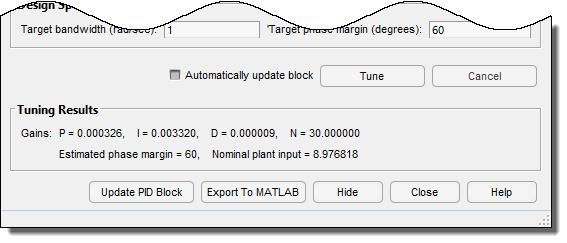
If Automatically update block is selected, the Frequency Response Based PID Tuner writes the new PID gains to the PID Controller block when tuning is completed. Otherwise, click Update PID Block to write the tuned gains to the block. Simulate the model to validate the tuned gains against your full nonlinear system.
For an example illustrating the use of the Frequency Response Based PID Tuner to tune a PID Controller block in a Simulink model that does not linearize, see Design PID Controller Using Plant Frequency Response Near Bandwidth.