Apply UDP Receive Block with Messages from Multiple IP Senders
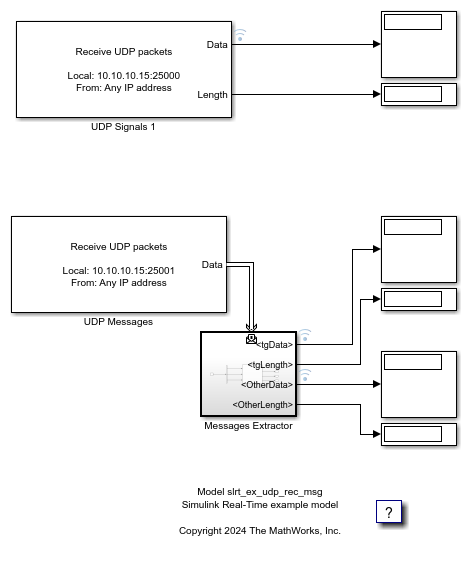
This example shows two possible ways to get the UDP data from the UDP Receive block, by using the signal (see upper signal flow in the model) or by using messages (see lower signal flow in the model). The message signal flow uses the Message Triggered Subsystem to get the message and divide the messages into two signals.
Open Model
model = 'slrt_ex_udp_rec_msg';
open_system(model);

Challenges with Signal-Based UDP Blocks
Some challenges occur when using a signal-based approach with the UDP Receive block for data from multiple IP addresses:
Data Accumulation: The socket accumulates too much data when the sender frequency is higher than the UDP Receive block sample frequency. This condition can leads to backlogs.
No IP Identification: The data is mixed from multiple source IP addresses. The model requires multiple blocks with unique ports to isolate source IP addresses.
Configuration Complexity: The model complexity increases with multiple source IP addresses. This complexity can make it hard to manage IP-specific data.
Advantages of Message-Based UDP Handling
Many of the challenges in a signal-based approach for handling data from multiple IP addresses are resolved by using a message-based approach with the UDP Receive block. The model can:
Use message-triggered subsystems to enable IP-based filtering. This filtering permits selective data routing without resorting to multiple UDP Receive blocks.
Handle packets immediately. The message-based approach lets you handle multiple packets in each time step, thus bypassing time-step delays.
Retain only the latest data by using a LIFO queue with size to 0, discarding any older packets so always processes the latest available data, minimizing the delay between data arrival and processing. Latency is reduced.
Handle multiple source IP addresses with a single UDP receive block via message-based routing. Port and block count are reduced.
The message contains the IP address and port of the sender. You can use that information in your model logic.
UDP Packet Bus
When you configure a UDP Receive block in message mode, a UDP_Packet is automatically created to wrap the incoming data using a bus, which groups the variables. This bus is generated in the workspace and adjusted automatically. These adjustments are helpful when you want to extract data using a Bus Selector, as shown in the example.
The UDP_Packet has a field called data, which is a fixed-size array determined by the Receive Width parameter in the block mask, and a length field that indicates the actual number of bytes received. If the incoming data exceeds the data array size, it gets truncated to fit. If it is less, it is filled with zeroes. This truncation or fill applies to signal mode and Message Mode, because both modes have the concept of a data and length.
View Method Comparison by Using the Simulation Data Inspector
This figure compares the signal-based and message-based approaches that the model uses to get data from the UDP Receive block. The signal-based approach (see upper signal flow in the model) data in the figure is labeled Graphic 1. The message-based approach (see lower signal flow in the model) data in the figure is labeled Graphic 2 and Graphic 3.

The message-based approach uses the Message Triggered Subsystem to get the message and divide the messages into two signals:
UDP datagrams from the target computer
UDP datagrams from other IP addresses
The message-based approach gets the UDP datagrams, and separates the datagrams from different IP addresses. To see the code that separates the datagrams, view the code in the MATLAB Function block in the model:
slrt_ex_udp_rec_msg/Messages Extractor/MATLAB Function
Note: The signal version of the block does not have an output for the IP of the datagram. All of the datagrams are combined as shown in Graphic 1.
The figure shows the data from the senders.
From Sender 1:
Sending a sine wave to the target computer IP by using port 25000 (received by the signal UDP, Graphic 1)
Sending a sine wave to the target computer IP by using port 25001 (received by the message UDP, Graphic 2)
From Sender 2:
Sending a sine wave to the target computer IP by using port 25000 (received by the signal UDP, Graphic 1)
Sending a sine wave to the target computer IP by using port 25001 (received by the message UDP, Graphic 3)
The figure shows:
The Graphic 1 combines the data of the sender 1 and 2 (port 25000), and the result is combined.
The Graphic 2 and Graphic 3 are extracted by analyzing the messages provided by the UDP block that receives the data from the sender 1 and 2 (port 25001) and it gets separated thanks to the use of the messages.
When the communication is stopped, the UDP message stops because it is pulling the data as they arrive, but the signal keeps pulling the data from the target computer socket at the model sample time.
Create Target Object and Connect
Create a Target object and connect to the default target computer.
tg = slrealtime;
connect(tg);
Configure Model
Open the example model. Configure STF selection. Configure IP address for UDP Receive blocks. Set stop time.
modelSTF = getSTFName(tg);
set_param(model,"SystemTargetFile",modelSTF);
targetIP = '192.168.7.5';
set_param([model,'/UDP Signals 1'],'ipAddress',targetIP);
set_param([model,'/UDP Messages'],'ipAddress',targetIP);
set_param(model,'StopTime','20');
Build, Load, and Run Real-Time Application
Build the real-time app. Use evalc to suppress build messages. Load and start the real-time application. Wait while application runs.
evalc('slbuild(model)');
load(tg,'slrt_ex_udp_rec_msg');
start(tg);
pause(25);
Close Model
bdclose(model);