Overview of Flexible Beams
Flexible Beam Blocks
You can use flexible beam blocks in the Simscape™ Multibody™ to model slender bodies with constant cross-sections that can have small and linear elastic deformations. These deformations include extension, bending, and torsion. To use these blocks, in the Library Browser, click Simscape > Multibody > Body Elements > Flexible Bodies > Beams.
The following figure shows a flexible channel beam model. In this example, the beam undergoes both bending and torsion under an applied transverse point load. The degree to which the beam bends and twists varies with the point of application of the force in the plane of the cross-section.
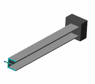
Flexible Channel Beam Model
To obtain the model files, open this example.
Beam Geometries
The geometry of a beam is an extrusion of its cross-section. The general cross-sections, with or without holes, are supported by the General Flexible Beam block. Additionally, the beam cross-section can take many standard shapes, such as channel, angle, and hollow cylindrical. For beams with standard cross-sectional shapes, use the following flexible beam blocks:
Flexible Cylindrical Beam (both solid and hollow)
Flexible Rectangular Beam (both solid and hollow)
Connection Frames
Each beam has two connection frames labeled A and B. Each connection frame has a frame port on the block that can connect to another block. The connection frames are located at the ends of the beam and fall on the z-axis of the local reference frame labeled R. The reference frame serves merely as an internal reference for the beam and has no frame port.
Deformation Models
In Simscape Multibody, all the flexible beams can have elastic bending, axial, and torsional deformations. The beams are assumed to be slender bodies whose length must far exceed its overall cross-sectional dimensions, and all the deformations should be linear and small.
The bending and axial deformations of a beam follow classical (Euler-Bernoulli) beam theory. The bending can be about any axis in the cross-sectional plane (xy-plane) of the beam. Cross-sectional slices are assumed to be rigid in-plane, to stay planar during deformation, and to always be perpendicular to the deformed neutral axis of the beam. The twisting of a beam derives from Saint-Venant torsion theory, and the cross-sectional slices are rigid in-plane but free to warp out-of-plane.
When one or more of these assumptions are not met, the result may be inaccurate. For example, in the figure, a cantilevered beam that is subjected to a transverse point load will get an inaccurate result when the bending deformation, δ, is large. During the bending, the free end of the beam moves downward perpendicularly instead of following the true physical path, which is indicated by the dotted trajectory. The discrepancy, ε, increases as the δ increases.
Reference Conditions
Flexible body blocks use the finite element (FE) based floating frame of reference (FFR) formulation [1] to model flexible bodies that have small and linear deformations superimposed on large rigid-body motions. The FE/FFR formulation uses a body frame of reference to capture the large rigid-body motion and defines elastic deformations relative to the fictitious undeformed body.
The degrees of freedom associated with the underlying finite element discretization include rigid body modes which leads to redundancy between the degrees of freedom of the body frame and the rigid-body motion included in the finite element model. To eliminate this redundancy, the blocks apply reference conditions to ensure that the reference coordinates fully and solely represent the rigid-body motion. Meanwhile, the remaining degrees of freedom represent purely elastic deformation.
Reference conditions are internal to the FFR model of a flexible body and do not externally constrain the body. To constrain the flexible body in the multibody system, use joints and other mechanical elements.
Different reference conditions impose different constraints between the flexible body and the corresponding body reference, which results in different sets of deformation mode shapes. To model the deformations more accurately, choose reference conditions that best align with the actual boundary conditions experienced by the flexible body.
The body-fixed reference conditions use a body-attached frame as the body frame of reference. In this situation, the deformation of the flexible body exhibits free vibration mode shapes that have zero translational and rotational deformation at the location of the body frame of reference.
For example, with a cantilever beam, you can attach the body frame of reference to either the fixed end or the free end. In both scenarios, the dashed rectangle indicates the fictitious undeformed body. For this particular set of cantilevered boundary conditions, attaching the body frame of reference at the fixed end is the better choice.
The linearized mean axes reference conditions place the body frame of reference at the instantaneous center of mass of the flexible body. The associated mode shapes of deformation correspond to the free vibration modes of the fully unconstrained body, excluding any rigid-body modes.
For example, this image shows a simply supported beam in bending, where the dashed rectangle represents the fictitious undeformed body that corresponds to the floating body frame of reference.
In this example, a viable alternative is to choose the midpoint frame to apply body-fixed reference conditions. In this scenario, the body frame of reference is not floating.
Stiffness and Inertia Properties
The block provides two ways to specify the stiffness and inertia properties
for a beam. To model a beam made of homogeneous, isotropic, and linearly elastic
material, in the Stiffness and Inertia section,
set the Type parameter to Calculate from
Geometry. Then specify the density, Young’s modulus, and
Poisson’s ratio or shear modulus. See the Derived Values
parameter for more information about the calculated stiffness and inertia
properties.
Alternatively, you can manually specify the stiffness and inertia properties,
such as flexural rigidity and mass moment of inertia density, by setting the
Type parameter to Custom.
Use this option to model a beam that is made of anisotropic materials. This
option decouples the mechanical properties from the beam cross section so you
can specify desired mechanical properties without capturing the details of the
exact cross section, such as fillet, rounds, chamfers, and tapers.
The manually entered stiffness properties must be calculated with respect to the frame located at the bending centroid. The frame must be in the same orientation as the beam reference frame. The stiffness matrix is
where:
is the axial stiffness along the beam.
is the centroidal bending stiffness about the x-axis.
is the centroidal bending stiffness about the y-axis.
is the torsional stiffness.
is the centroidal cross bending stiffness.
The manually entered inertia properties must be calculated with respect to a frame located at the center of mass. The frame must be in the same orientation as the beam reference frame. The mass matrix includes rotatory inertia
where:
is the mass per unit length.
is the mass moment of inertia density about the x-axis.
is the mass moment of inertia density about the y-axis.
is the polar mass moment of inertia density.
is the mass product of inertia density.
The beam block uses the classical beam theory where the relation between sectional strains and stress resultants is
where:
is the axial force along the beam.
is the bending moment about the x-axis.
is the bending moment about the y-axis.
is the torsional moment about the z-axis.
is the axial strain along the beam.
is the bending curvature about the x-axis.
is the bending curvature about the y-axis.
is the torsional twist about the z-axis.
Damping Methods
The beam blocks support two damping methods: uniform modal damping and proportional damping. The uniform modal damping method applies identical damping ratios to all the vibration modes of the beam. In the proportional damping method, the damping matrix [C] is a linear combination of the mass matrix [M] and the stiffness matrix [K]:
,
where α and β are scalar coefficients.
Discretization
The Number of Elements parameter in the Discretization section of the beam block dialog box specifies the number of finite elements used to discretize the beam. You can select its value to obtain a good compromise between simulation accuracy, which may require more elements, and simulation speed, which requires fewer elements. Use the fewest elements needed to satisfy your accuracy requirements.
For bending deformations, the beam blocks use the cubic Hermite interpolation method to compute the displacement distributions throughout each element. The distributions of axial displacement and torsional rotation are obtained by linear interpolation method.
Simulation Performance
When using beam blocks in a model, several factors impact the accuracy and speed of the simulation performance. This section discusses the impact of the three most important factors: flexible beam usage, solver selection, and damping settings.
Even though using flexible beams can increase the accuracy of a multibody simulation, the flexible beams tend to slow it down by increasing the numerical stiffness and the number of degrees of freedom of the system. To speed up the simulation, you should use a rigid body whenever the deformation of the body is negligible. Moreover, the Number of Elements parameter in the Discretization section heavily impacts the performance of the simulation. For more information, see the Discretization section.
The solver is critical to the performance of a multibody simulation. The stiff solvers, such as ode15s, ode23t, or daessc, tend to work better for systems with flexible beams due to the stiff nature of these systems. Additionally, solver tolerances and maximum order also impact the accuracy and speed of the simulation. For more information, see Choose a Solver.
Note
All the solvers, except ode23t, provide some level of numerical dissipation, which can be helpful for modeling flexible multibody systems.
When modeling a flexible beam with little or no damping, undesirable high-frequency modes in the response can slow down the simulation if the solver does not already provide adequate numerical dissipation. In that case, adding a small amount of damping can improve the speed of the simulation without significantly affecting the accuracy of the model.
Deformation Under Gravity
Flexible beams in Simscape Multibody respond to gravity, but only that specified in the Mechanism Configuration block. The force due to a Gravitational Field block is ignored. If the frame network of which the flexible beam block is a part contains a Gravitational Field block, the body behaves as though in zero gravity. Using flexible body and Gravitational Field blocks in the same frame network causes Diagnostic Viewer to issue a compilation warning.
Note
Modeling gravity with both the Mechanism Configuration and Gravitational Field blocks results in a compilation error.
Visualization
The dialog box of each flexible beam block contains a collapsible visualization pane. This pane provides instant visual feedback on the beam you are modeling. Use it to find and fix any issues with the cross-section, length, and color of the beam. You can examine the beam from different views by selecting a standard view or by rotating, panning, and zooming.
In the toolstrip of the visualization pane, click the Update Visualization button to view the latest changes to the beam. Click Apply or OK to commit any changes to the model.
Note
You can point to any button to see its function.
Additionally, you can right-click the visualization pane for a context-sensitive menu. This menu provides additional options to change the background color, modify the view convention setting, and split the visualization pane into multiple windows that display different views of the beam.
References
[1] Shabana, Ahmed A. Dynamics of Multibody Systems. Fourth edition. New York: Cambridge University Press, 2014.
[2] Agrawal, Om P., and Ahmed A. Shabana. “Dynamic Analysis of Multibody Systems Using Component Modes.” Computers & Structures 21, no. 6 (January 1985): 1303–12. https://doi.org/10.1016/0045-7949(85)90184-1.