Model Gravity in a Planetary System
This tutorial shows how to simulate the gravity-driven orbits of the major solar system bodies. The model treats the sun and planets as perfect spheres each with three translational degrees of freedom. Planet spin is ignored. Gravitational fields generate the forces that keep the planets in orbit.

Spherical Solid blocks represent the solar system bodies and provide their geometries, inertias, and colors. Cartesian Joint blocks define the bodies’ degrees of freedom relative to the world frame, located at the solar system barycenter. Gravitational Field blocks add the long-range forces responsible for bending the initial planet trajectories into closed elliptical orbits.
The Cartesian Joint blocks provide the initial states—positions and velocities—of the sun and planets relative to the world frame. The initial states correspond to the solar system configuration on Jun 20th, 2016. They are sourced from ephemeris databases maintained by the Jet Propulsion Laboratory (JPL).
You can query the databases through the JPL Horizons system using a web or telnet interface. Aerospace Toolbox users can alternatively obtain the ephemeris data at the MATLAB® command prompt using the planetEphemeris function after installing the Aerospace Ephemeris Data support package.
Start a New Model
Open the Simscape™ Multibody™ model template and remove all unnecessary blocks. Modify the gravity settings so that you can add gravitational fields to the model. The result provides a starting point for the solar system model.
At the MATLAB command prompt, enter
smnew. MATLAB opens a model template with commonly used blocks and suitable solver settings for Simscape Multibody models.Cut all but the Mechanism Configuration, Solver Configuration, and World Frame blocks. These three blocks provide the model with gravity settings, solver settings, and a global inertia reference frame.
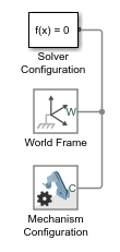
In the Mechanism Configuration block dialog box, set Uniform Gravity to
None. This setting enables you to model gravity as an inverse-square law force using Gravitational Field blocks instead.
Add the Solar System Bodies
Represent the solar system bodies using Spherical Solid blocks. Specify the geometry and inertia parameters in terms of MATLAB variables and initialize these variables in the model workspace using Model Explorer. The variables are data structures named after the solar system bodies using proper-noun capitalization.
Connect and Configure the Solid Blocks
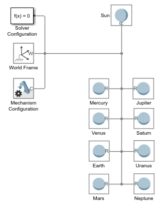
Add to the model nine Spherical Solid blocks from the Body Elements library. The blocks represent the sun and eight known planets.
Connect and name the blocks as shown in the figure. The branched frame connection line between the world frame and the planets makes them rigidly connected and coincident in space. You later change this condition using Cartesian Joint blocks.
In the Spherical Solid block dialog boxes, set the Inertia > Based on parameter to
Mass. The inertia parameter setting enables you to specify the solid mass directly so that you can scale the planet shapes without affecting the model dynamics.Specify the following Spherical Solid block parameters in terms of MATLAB data structure fields. Enter the field names in the format Structure.Field, where Structure is the title-case name of the solar system body and Field is the string shown in the table—e.g.,
Sun.RorEarth.RGB.

You later define the new structure fields in the model workspace using Model Explorer.
Add the Solid Property Initialization Code
In the Modeling tab, click Model Explorer.
In the Model Hierarchy pane of Model Explorer, expand the node for your model and select Model Workspace. The Model Hierarchy pane is on the left side.
In the Model Workspace pane of Model Explorer, set Data Source to
MATLAB Code. The Model Workspace pane is on the right side.In the MATLAB Code field, add the initialization code for the sun and planet solid properties. The code is organized into sections named after the solar system bodies. You later add the initial position and velocity data to these sections.
% All values are in SI units.
% RGB color vectors are on a normalized 0-1 scale.
% Body dimensions are scaled for visualization purposes.
% Scaling has no impact on model dynamics.

% Scaling
SunScaling = 0.5e2;
TerrestrialPlanetScaling = 1.2e3;
GasGiantScaling = 2.5e2;

% Sun
Sun.M = 1.99e30;
Sun.R = 6.96e8*SunScaling;
Sun.RGB = [1 0.5 0];

% Mercury
Mercury.M =3.30e23;
Mercury.R = 2.44e6*TerrestrialPlanetScaling;
Mercury.RGB = [0.5 0.5 0.5];

% Venus
Venus.M = 4.87e24;
Venus.R = 6.05e6*TerrestrialPlanetScaling;
Venus.RGB = [1 0.9 0];

% Earth
Earth.M = 5.97e24;
Earth.R = 6.05e6*TerrestrialPlanetScaling;
Earth.RGB = [0.3 0.6 0.8];

% Mars
Mars.M = 6.42e23;
Mars.R = 3.39e6*TerrestrialPlanetScaling;
Mars.RGB = [0.6 0.2 0.4];

% Jupiter
Jupiter.M = 1.90e27;
Jupiter.R = 6.99e7*GasGiantScaling;
Jupiter.RGB = [0.6 0 0.3];

% Saturn
Saturn.M = 5.68e26;
Saturn.R = 5.82e7*GasGiantScaling;
Saturn.RGB = [1 1 0];

% Uranus
Uranus.M = 8.68e25;
Uranus.R = 2.54e7*GasGiantScaling;
Uranus.RGB = [0.3 0.8 0.8];

% Neptune
Neptune.M = 1.02e26;
Neptune.R = 2.46e7*GasGiantScaling;
Neptune.RGB = [0.1 0.7 0.8];
Click Reinitialize from Source.
The Spherical Solid blocks now have all the numerical data they need to render the planet shapes and colors. Try opening a Spherical Solid block dialog box and verify that a sphere now appears in the solid visualization pane.

Add the Degrees of Freedom
Add three translational degrees of freedom between the solar system barycenter and each solar system body using Cartesian Joint blocks. You later use these blocks to specify the initial positions and velocities of the solar system bodies.
Add to the model nine Cartesian Joint blocks from the Joints library. The blocks provide the translational degrees of freedom of the sun and eight known planets.
Connect and name the blocks as shown in the figure. If you place a block on an existing connection line, Simscape Multibody software automatically connects the block to that line. Flip and rotate the joint blocks to ensure that Spherical Solid blocks connect only to follower (F) frame ports.
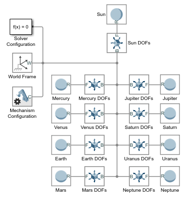
The sun and planets are no longer rigidly connected. They can now translate relative to each other. They are, however, still coincident in space. To place them at different initial positions and give them initial velocities, you must specify the joint state targets.
Add the Initial State Targets
Specify the sun and planet initial states in terms of MATLAB variables using the Cartesian Joint blocks in your model. Then, initialize the new MATLAB variables in the model workspace using Model Explorer. You define the MATLAB variables as new fields in the existing data structures.
Configure the Cartesian Joint Blocks
In the Cartesian Joint block dialog boxes, check the State Targets > Specify Position Target and State Targets > Specify Velocity Target checkboxes for the X, Y, and Z prismatic joint primitives. These settings enable you to specify the desired initial states of the sun and planets.
Specify the Cartesian Joint state target values for the X, Y, and Z prismatic joint primitives in terms of MATLAB structure fields. Enter the field names in the format Structure.Field, where Structure is the title-case name of the solar system body and Field is the string shown in the table—e.g.,
Sun.PxorEarth.Vz.

You later define the new structure fields in the model workspace using Model Explorer.
Add the State Target Initialization Code
In the Modeling tab, click Model Explorer.
In the Model Hierarchy pane of Multibody Explorer, expand the node for your model and select Model Workspace. The Model Hierarchy pane is on the left side.
In the Model Workspace pane of Model Explorer, set Data Source to
MATLAB Code. The Model Workspace pane is on the right side.In the MATLAB Code field, add the initialization code for the joint state targets. The new code, shown in blue, consists of the position and velocity components obtained from the JPL ephemeris databases. You can copy just the new code or replace your entire model workspace code with that shown.
% All values are in SI units.
% RGB color vectors are on a normalized 0-1 scale.
% Body dimensions are scaled for visualization purposes.
% Scaling has no impact on model dynamics.

% Scaling
SunScaling = 0.5e2;
TerrestrialPlanetScaling = 1.2e3;
GasGiantScaling = 2.5e2;

% Sun
Sun.M = 1.99e30;
Sun.R = 6.96e8*SunScaling;
Sun.RGB = [1 0.5 0];
Sun.Px = 5.5850e+08;
Sun.Py = 5.5850e+08;
Sun.Pz = 5.5850e+08;
Sun.Vx = -1.4663;
Sun.Vy = 11.1238;
Sun.Vz = 4.8370;

% Mercury
Mercury.M =3.30e23;
Mercury.R = 2.44e6*TerrestrialPlanetScaling;
Mercury.RGB = [0.5 0.5 0.5];
Mercury.Px = 5.1979e+10;
Mercury.Py = 7.6928e+09;
Mercury.Pz = -1.2845e+09;
Mercury.Vx = -1.5205e+04;
Mercury.Vy = 4.4189e+04;
Mercury.Vz = 2.5180e+04;

% Venus
Venus.M = 4.87e24;
Venus.R = 6.05e6*TerrestrialPlanetScaling;
Venus.RGB = [1 0.9 0];
Venus.Px = -1.5041e+10;
Venus.Py = 9.7080e+10;
Venus.Pz = 4.4635e+10;
Venus.Vx = -3.4770e+04;
Venus.Vy = -5.5933e+03;
Venus.Vz = -316.8994;

% Earth
Earth.M = 5.97e24;
Earth.R = 6.05e6*TerrestrialPlanetScaling;
Earth.RGB = [0.3 0.6 0.8];
Earth.Px = -1.1506e+09;
Earth.Py = -1.3910e+11;
Earth.Pz = -6.0330e+10;
Earth.Vx = 2.9288e+04;
Earth.Vy = -398.5759;
Earth.Vz = -172.5873;

% Mars
Mars.M = 6.42e23;
Mars.R = 3.39e6*TerrestrialPlanetScaling;
Mars.RGB = [0.6 0.2 0.4];
Mars.Px = -4.8883e+10;
Mars.Py = -1.9686e+11;
Mars.Pz = -8.8994e+10;
Mars.Vx = 2.4533e+04;
Mars.Vy = -2.7622e+03;
Mars.Vz = -1.9295e+03;

% Jupiter
Jupiter.M = 1.90e27;
Jupiter.R = 6.99e7*GasGiantScaling;
Jupiter.RGB = [0.6 0 0.3];
Jupiter.Px = -8.1142e+11;
Jupiter.Py = 4.5462e+10;
Jupiter.Pz = 3.9229e+10;
Jupiter.Vx = -1.0724e+03;
Jupiter.Vy = -1.1422e+04;
Jupiter.Vz = -4.8696e+03;

% Saturn
Saturn.M = 5.68e26;
Saturn.R = 5.82e7*GasGiantScaling;
Saturn.RGB = [1 1 0];
Saturn.Px = -4.2780e+11;
Saturn.Py = -1.3353e+12;
Saturn.Pz = -5.3311e+11;
Saturn.Vx = 8.7288e+03;
Saturn.Vy = -2.4369e+03;
Saturn.Vz = -1.3824e+03;

% Uranus
Uranus.M = 8.68e25;
Uranus.R = 2.54e7*GasGiantScaling;
Uranus.RGB = [0.3 0.8 0.8];
Uranus.Px = 2.7878e+12;
Uranus.Py = 9.9509e+11;
Uranus.Pz = 3.9639e+08;
Uranus.Vx = -2.4913e+03;
Uranus.Vy = 5.5197e+03;
Uranus.Vz = 2.4527e+03;

% Neptune
Neptune.M = 1.02e26;
Neptune.R = 2.46e7*GasGiantScaling;
Neptune.RGB = [0.1 0.7 0.8];
Neptune.Px = 4.2097e+12;
Neptune.Py = -1.3834e+12;
Neptune.Pz = -6.7105e+11;
Neptune.Vx = 1.8271e+03;
Neptune.Vy = 4.7731e+03;
Neptune.Vz = 1.9082e+03;
Click Reinitialize from Source.
The model now has the numerical data it needs to assemble the planets in the position coordinates obtained from the JPL databases. However, a model simulation at this point would show the planets moving in straight-line trajectories. To obtain elliptical orbits, you must complete the model by adding the sun and planet gravitational fields.
Add the Gravitational Fields
Model the gravitational pull of each solar system body using the Gravitational Field block. This block automatically computes the gravitational pull of a body on all other bodies using Newton’s law of universal gravitation.
In each Spherical Solid block dialog box, expand the Frames area and click the Create button.
Set the Frame Name parameter to
R2and click the Save button. The new frame is an exact copy of the reference frame but has a separate frame port. You can use these ports to connect the gravitational field blocks while avoiding crossed connection lines.Add to the model nine Gravitational Field blocks from the Forces and Torques library. The blocks provide the gravitational forces that each solar system body exerts on all other bodies.
Connect and name the blocks as shown in the figure. Ensure that the blocks connect directly to the Spherical Solid blocks. Such a connection ensures that the fields are centered on the solid spheres and rigidly connected to them.
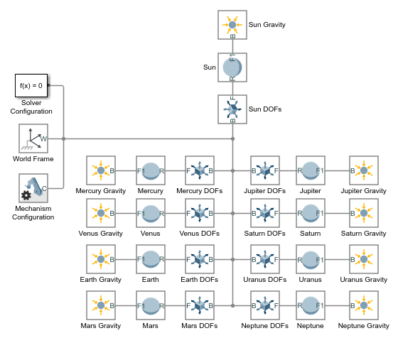
In the Gravitational Field blocks, specify the Mass parameter as MATLAB structure field names. Enter the field names in the format Structure.Field, where Structure is the title-case name of the solar system body and Field is the string
M—e.g.,Sun.MorEarth.M. These fields have been previously defined in the model workspace.
Configure and Run the Simulation
Configure the Simulink® solver settings to capture ten earth revolutions in a single simulation. Then, simulate the model and view the resulting solar system animation. Configure the animation settings to play the ten-year animation in the period of a few seconds.
Configure the Solver Settings
Open the Configuration Parameters. In the Modeling tab, click Model Settings.
Set the Stop time parameter to
10*365*24*60*60. This number, equal to ten years in seconds, allows you to simulate a full ten earth revolutions from Jun 20th, 2016 through Jun 20th, 2026.Set the Max step size parameter to
24*60*60. This number, equal to one day in seconds, is small enough to provide smooth animation results. Increase this number if you prefer faster simulation results.
Update and Simulate the Model
Update the block diagram. In the Modeling tab, click Update Model. Multibody Explorer opens with a static 3-D display of the model in its initial state. Check that the sun and planets appear in the visualization pane and that their relative dimensions and positions are reasonable.
Run the simulation. Multibody Explorer plays an animation of the solar system. Note that at the default base playback speed, the planets appear static. You must increase this speed in the Multibody Explorer animation settings.
Configure the Animation Settings
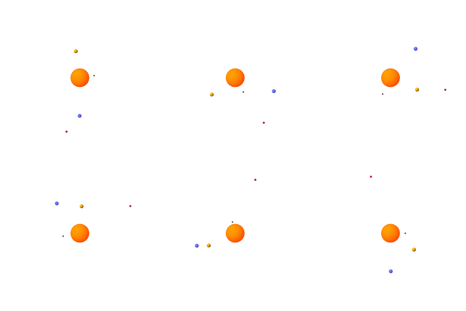
In Multibody Explorer, navigate to the bottom of the visualization pane. Adjust the playback speed setting from 1 x to 3,153,600 x. This speed corresponds to one earth revolution every ten seconds.
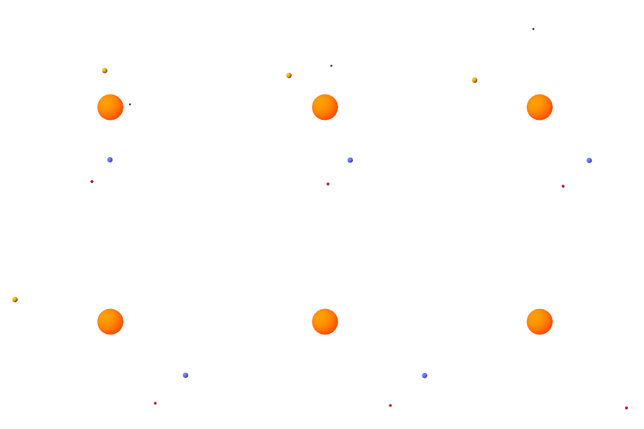
Pause and play the animation to apply the new base playback speed. The figure shows the animation results at the new speed.
Open an Example Model
To see the complete solar system model, at the MATLAB command prompt, enter:
open_system("DocGravitationalField")
See Also
smnew | Gravitational Field | Mechanism Configuration | Spherical
Solid | Cartesian Joint