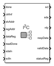
Main Content

I2C Master

Configure and communicate with I2C slave device

  • I2C Master block

Libraries:
SoC Blockset / Hardware Logic I/O

Description

The I2C Master block configures and communicates with an inter-integrated circuit communications (I2C) slave device connected to a field programmable gate array (FPGA). This block contains an I2C master controller with an AXI-Lite interface to perform the configuration.

The I2C Master block supports these features:

  • AXI4-Lite interface support for configuration and access

  • Single-master and multi-slave support

  • Support 7-bit and 10-bit address I2C slave devices

  • Burst mode support with a maximum burst size of 256 bytes

  • Support multiple transmission speed modes

  • An HDL-IP compatible model with code generation capability

The block uses the AXI-Lite interface to configure and create a control path interface to communicate with an I2C slave device. The hardware generated from the generation process contains an AXI-Lite register interface and two hardware interfaces, serial clock (SCL), and serial data (SDA). SCL and SDA connect the I2C Master block and the slave device.

Each port represented in the block is an AXI-Lite register, except the sdaIn, sclIn, scl, and sda ports. To communicate with a slave device, the AXI-Lite register interface configures the register information in the I2C Master block. This table contains the I2C Master AXI-Lite register information.

Register AddressPort and Register NameRegister Size in BitsOperation Mode
0x100ctrlInf — Control information

32

Write
0x104slvAddr — Slave address

32

Write
0x108regAddr — Register address

32

Write
0x10CdataReg — Data register

32

Write
0x110readDone — Read done register32Write
0x114done — Done register

32

Write
0x118rdy — Ready register32Read
0x11CrespData — First response data register32Read
0x120validData — Response data valid register32Read
0x124statusReg — Status register32Read

To perform read and write operations using the I2C Master block, you need to follow a proper sequence. This section provides information about the sequence flow for read and write operations.

Read Sequence

To read data from an external slave device:

  1. Send the ctrlInf register information.

  2. Send the slvAddr register information.

  3. Send the regAddr register information.

  4. Set the done register to 1 after sending one set of register information to the block and then set it to 0.

  5. Read the response data from the external slave device. After reading the data from the respData register, set the readDone register to 1 and then set it to 0 immediately.

  6. Set the readDone register to 1 again, to read more than 4 bytes of data. After the read operation, set it to 0 immediately.

In read sequence, one set of register information is a combination of ctrlInf, slvAddr, and regAddr registers.

Write Sequence

To write data to an external slave device:

  1. Send the ctrlInf register information.

  2. Send the slvAddr register information.

  3. Send the regAddr register information.

  4. Send the dataReg register that contains the data to write to the slave device register.

  5. Set the done register to 1 after writing one set of register information to the block, and then set it to 0.

  6. Set the done register to 1 again, to write more than 4 bytes of data. After the write operation, set it to 0 immediately.

In write sequence, one set of register information is a combination of ctrlInf, slvAddr, regAddr, and dataReg registers.

Ports

Input

expand all

Control information register contains configuration information on how the block communicates with the slave device, specified as a scalar. This register is a combination of read or write operation indication bit, number of bytes of slave-device register address, number of bytes of slave-device data register, and slave device address type bit. You can modify the configuration based on your requirement.

BitPurposeValue Description
0Set write or read mode.

To write to the slave-device register, set this value to 0. To read from the slave-device register, set this value to 1.

[2:1]Set the size of the slave-device register address.

If the slave-device register address size is:

  • One byte (8 bits), set this value to 00

  • Two bytes (16 bits), set this value to 01

  • Three bytes (24 bits), set this value to 10

  • Four bytes (32 bits), set this value to 11

[10:3]Set the data size of the slave-device register.

If the slave-device register supports:

  • One byte of data, set this value to 00000000

  • Two bytes of data, set this value to 00000001

  • Three bytes of data, set this value to 00000010

  • Four bytes of data, set this value to 00000011

  • Five bytes of data, set this value to 00000100

  • Six bytes of data, set this value to 00000101

  • Seven bytes of data, set this value to 00000110

  • Eight bytes of data, set this value to 00000111

  • Nine bytes of data, set this value to 00001000

  • Ten bytes of data, set this value to 00001001

  • Eleven bytes of data, set this value to 00001010

  • Twelve bytes of data, set this value to 00001011

  • Thirteen bytes of data, set this value to 00001100

  • Fourteen bytes of data, set this value to 00001101

  • Fifteen bytes of data, set this value to 00001110

  • Sixteen bytes of data, set this value to 00001111

….…....

  • 256 bytes of data, set this value to 11111111

11Set the slave device type

To configure 7-bit address slave device, set this value to 0. To configure 10-bit address slave device, set this value to 1.

Data Types: uint16

Slave-address register that contains the address of the slave device, specified as a scalar.

Data Types: uint16

Register address of the slave device, specified as a scalar.

Data Types: uint32

Data register, specified as a scalar. The block uses this port to write data to the slave-device register.

Data Types: uint32

Read done signal, specified as a Boolean scalar. When this value is 1 (true), the user is ready to read the response data from the block that is received from the slave device. When this value is 0 (false), the user is not ready to read the response data from the block.

Data Types: Boolean

Done signal, specified as a Boolean scalar. This value indicates the block when to read the AXI-Lite register information.

Data Types: Boolean

Input serial data, returned as a Boolean scalar. This port provides a serial data signal to the block from the slave device.

Data Types: Boolean

Input serial clock, returned as a Boolean scalar. This port provides a serial clock signal to the block from the slave device.

Data Types: Boolean

Output

expand all

Output serial clock, specified as a Boolean scalar. This port provides a serial clock signal from the block to the slave device.

Data Types: Boolean

Output serial data, specified as a Boolean scalar. This port provides a serial data signal from the block to the slave device.

Data Types: Boolean

Ready signal, returned as a Boolean scalar. When this value is 1 (true), the block is ready to accept the configuration data. When this value is 0 (false), the block is not ready to accept the configuration data.

Data Types: Boolean

Response data register containing the data from the slave-device register, returned as a scalar.

Data Types: uint32

Control signal that indicates if the response data is valid, returned as a Boolean scalar. When this value is 1 (true), the response data from response data registers is valid. When this value is 0 (false), the response data from response data registers is not valid.

Data Types: Boolean

Indicates the status of the I2C bus, returned as a scalar.

BitPurposeValue Description
[7:4]Reserved

Reserved

3Indicates the status of the I2C bus.

When this value is 1, it indicates that the I2C bus is busy. When this value is 0, it indicates that the I2C bus is idle and ready for configuration.

2Indicates the acknowledgment status from the slave device to the I2C Master.

When this value is 1, it indicates that the slave device has not acknowledged the I2C Master. When this value is 0, it indicates that the slave device has acknowledged the I2C Master.

[1:0]ReservedReserved

Data Types: uint32

Parameters

expand all

Specify the speed mode as one of these values:

  • Standard Mode — Supports frequencies up to 100 KHz

  • Fast Mode — Supports frequencies up to 400 KHz

  • Fast Plus Mode — Supports frequencies up to 1 MHz

Extended Capabilities

Fixed-Point Conversion
Design and simulate fixed-point systems using Fixed-Point Designer™.

Version History

Introduced in R2019a

expand all