Average-Value Rectifier (Three-Phase)
Average-value three-phase AC voltage to DC voltage converter with fixed power loss
Libraries:
Simscape /
Electrical /
Semiconductors & Converters /
Converters
Description
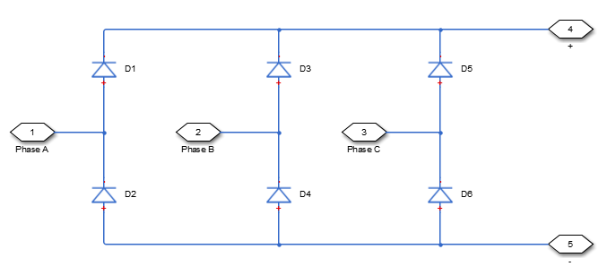
The Average-Value Rectifier (Three-Phase) block models an average-value, full-wave, six-pulse rectifier. It converts instantaneous three-phase AC voltages to DC voltage and DC power demand to three-phase AC power demand. The corresponding AC power demand is equal to the sum of the fixed power loss and the DC power demand.
You can use the Average-Value Rectifier (Three-Phase) block only as a six-pulse rectifier. You cannot combine two Average-Value Rectifier blocks to represent a twelve-pulse rectifier.
The figure shows the equivalent circuit for the rectifier as a full-wave, six-pulse rectifier. The Average-Value Rectifier (Three-Phase) block does not yield the harmonics that are typically associated with the detailed representation, however, because it performs an average-value power conversion.

This block can work in both time and frequency-and-time simulation modes. If you set
the AC frequency parameter to Variable,
this block works only in time simulation mode. If you select
Constant, this block works in both time and
frequency-time simulation modes. For more information, see Frequency and Time Simulation Mode.
Electrical Defining Equations
The voltages are defined by:
and
where:
va, vb, vc are the respective AC phase voltages.
vref is the DC offset on the AC side. In a balanced AC power system with no DC bias, vDC is
0V.VRMS is the RMS AC line-line voltage.
vDC is the voltage difference between the positive and negative terminals of the rectifier.
is the vDC /VRMS ratio for a full-wave, six-pulse rectifier.
vp, vn are the voltages at the positive and negative terminals of the rectifier.
The resistance, power, and currents are defined by
and
where:
VRated is the rated AC voltage that you specify on the block mask.
Pfixed is the fixed power loss that you specify on the block mask.
Rfixed is the fixed per-phase series resistance in an equivalent wye-connected load.
ip, in are the currents flowing into the positive and negative terminals of the rectifier.
PDC is the power output on the DC side. PDC has a minimum limit of
0W.RAC is the per-phase series resistance in an equivalent wye-connected load.
ia, ib, ic are the respective AC phase currents flowing into the rectifier.

