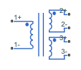
Three-Winding Mutual Inductor
Three coupled inductors
Libraries:
Simscape /
Electrical /
Passive /
Transformers
Description
The Three-Winding Mutual Inductor block represents a set of three coupled inductors or windings. The voltage across the three windings is
where:
Vi is voltage across the ith winding.
Ii is current through the ith winding.
Li is self inductance of the ith winding.
Mij is mutual inductance of the ith and jth windings, .
In these equations, currents are positive when flowing into the positive node of their respective inductor terminals.
To set the coefficients of coupling to 1 while also retaining the correct low-frequency behavior, blocking DC, select the Perfect coupling - no leakage parameter (since R2025a).
Simscape™ and Simscape Electrical™ libraries include several blocks than can model the same type of transformer device. However, these blocks make different modeling assumptions. To choose the right block for your application, you must understand how these assumptions impact the block behavior as a function of frequency. For more information, see Choose Blocks to Model Transformers.
When you run a simulation that includes this block, the software checks the specified parameter values to ensure that the resulting device is passive. If it is not, the software issues an error.
Variables
To set the priority and initial target values for the block variables before simulation, use the Initial Targets section in the block dialog box or Property Inspector. For more information, see Set Priority and Initial Target for Block Variables.
Use nominal values to specify the expected magnitude of a variable in a model. Using system scaling based on nominal values increases the simulation robustness. Nominal values can come from different sources. One of these sources is the Nominal Values section in the block dialog box or Property Inspector. For more information, see System Scaling by Nominal Values.
Examples

DC-DC LLC Converter
A DC-DC LLC power converter with frequency control. The Controller block implements a simple integral control in Simulink®. This integral control achieves a nominal output voltage, specified in the variable Vout_nominal. The Output scope shows the frequency control signal, the output voltage, and the reference value for the output voltage. During startup, the reference value ramps up to its desired setpoint. The design of the LLC powertrain is computed automatically using the first harmonic approximation.

Class E DC-DC Converter
A Class E power converter with frequency control. A simple integral control is implemented in Simulink® in the Controller block, and is designed to deliver 100W into a 5ohm load. The switch is an LDMOS, high-voltage transistor with a nonlinear capacitance model, and R Trans is the equivalent series resistance of the transformer. The Output scope shows the drain-source voltage for evaluation of the voltage stress on the switch. Note that, due to the nonlinear output capacitance of the transistor, the peak voltage stress is higher than would be expected if the output capacitance were constant. In addition, the scope also shows the frequency control signal, the output voltage, and the reference value for the output voltage. This model can be used to calculate the output power information from components in the circuit.

Band-Pass Filter Using Three Mutually-Coupled Inductors
An implementation of a band-pass filter using three mutually-coupled inductors. The model can be used to validate filter parameters which are chosen to provide a band-pass centered on 100MHz. A band-limited noise source is up-shifted by a 100MHz oscillator and applied to the filter. The response is then down-shifted by the oscillator. The model StopFcn callback takes FFTs of the source and response and estimates the filter frequency response.