Main Content

Three-Winding Nonlinear Transformer

Single-phase nonlinear three-winding transformer

Since R2019b

  • Three-Winding Nonlinear Transformer block

Libraries:
Simscape / Electrical / Passive / Transformers

Description

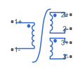
The Three-Winding Nonlinear Transformer block represents a single-phase, nonlinear, three-winding transformer with a nonideal core. A core may be nonideal due to its magnetic properties or dimensions. This figure shows the equivalent circuit topology:

where:

  • R1 is the primary winding resistance.

  • L1 is the primary leakage inductance.

  • R2 is the first secondary winding resistance.

  • L2 is the first secondary leakage inductance.

  • R3 is the second secondary winding resistance.

  • L3 is the second secondary leakage inductance.

  • Rm is the magnetization resistance.

  • Lm is the magnetization inductance.

The block provides the following parameterization options for the nonlinear magnetization inductance:

  • Single inductance (linear)

  • Single saturation point

  • Magnetic flux versus current characteristic

  • Magnetic flux density versus magnetic field strength characteristic

  • Magnetic flux density versus magnetic field strength characteristic with hysteresis

For more information, see the Nonlinear Inductor block reference page.

Ports

Conserving

expand all

Electrical conserving port associated with the positive terminal of line 1.

Electrical conserving port associated with the negative terminal of line 1.

Electrical conserving port associated with the positive terminal of line 2.

Electrical conserving port associated with the negative terminal of line 2.

Electrical conserving port associated with the positive terminal of line 3.

Electrical conserving port associated with the negative terminal of line 3.

Parameters

expand all

Main

Number of turns of wire on the first primary winding of the transformer.

Number of turns of wire on the first secondary winding of the transformer.

Number of turns of wire on the second secondary winding of the transformer.

Resistance for R1, which represents the power loss of the primary winding.

Inductance for L1, which represents the magnetic flux loss of the primary winding.

Resistance for R2, which represents the power loss of the first secondary winding.

Inductance for L2, which represents the magnetic flux loss of the first secondary winding.

Resistance for R3, which represents the power loss of the second secondary winding.

Inductance for L3, which represents the magnetic flux loss of the second secondary winding.

Magnetization

Resistance for Rm, which represents the magnetic losses in the transformer core.

Method of the nonlinear magnetization inductance parameterization:

  • Single inductance (linear) — Provide the unsaturated inductance value.

  • Single saturation point — Provide the values for the unsaturated and saturated inductances, as well as saturation magnetic flux. This is the default option.

  • Magnetic flux versus current characteristic — Provide the current vector and the magnetic flux vector, and then populate the magnetic flux versus current lookup table.

  • Magnetic flux density versus field strength characteristic — Provide the values for effective core length, cross-sectional area, magnetic field strength vector and the magnetic flux density vector, and then populate the magnetic flux density versus magnetic field strength lookup table.

  • Magnetic flux density versus field strength characteristic with hysteresis — Define magnetic flux density as a function or both the current value and the history of the field strength by providing the number of turns, the effective core length and cross-sectional area, the initial anhysteretic B-H curve gradient, the magnetic flux density and field strength at a certain point on the B-H curve, the coefficient for the reversible magnetization, the bulk coupling coefficient, and the inter-domain coupling factor.

Value of inductance used when the magnetization inductance Lm is operating in its linear region.

Dependencies

To enable this parameter, set the Magnetization inductance parameterized by parameter to Single inductance (linear) or Single saturation point.

Value of inductance used when the magnetization inductance Lm is operating beyond its saturation point.

Dependencies

To enable this parameter, set the Magnetization inductance parameterized by parameter to Single saturation point.

Value of magnetic flux at which the magnetization inductance Lm saturates.

Dependencies

To enable this parameter, set the Magnetization inductance parameterized by parameter to Single saturation point.

Current data used to populate the magnetic flux versus current lookup table.

Dependencies

To enable this parameter, set the Magnetization inductance parameterized by parameter to Magnetic flux versus current characteristic.

Magnetic flux data used to populate the magnetic flux versus current lookup table.

Dependencies

To enable this parameter, set the Magnetization inductance parameterized by parameter to Magnetic flux versus current characteristic.

Magnetic field strength data used to populate the magnetic flux density versus magnetic field strength lookup table.

Dependencies

To enable this parameter, set the Magnetization inductance parameterized by parameter to Magnetic flux density versus field strength characteristic.

Magnetic flux density data used to populate the magnetic flux density versus magnetic field strength lookup table.

Dependencies

To enable this parameter, set the Magnetization inductance parameterized by parameter to Magnetic flux density versus field strength characteristic.

Effective core length, also defined as the average distance of the magnetic path around the transformer core.

Dependencies

To enable this parameter, set the Magnetization inductance parameterized by parameter to Magnetic flux density versus field strength characteristic.

Effective core cross-sectional area, also defined as the average area of the magnetic path around the transformer core.

Dependencies

To enable this parameter, set the Magnetization inductance parameterized by parameter to Magnetic flux density versus field strength characteristic.

Gradient of the anhysteretic B-H curve around zero field strength. Set this parameter to the average gradient of the positive-going and negative-going hysteresis curves.

Dependencies

To enable this parameter, set the Magnetization inductance parameterized by parameter to Magnetic flux density versus field strength characteristic with hysteresis.

Specify a point on the anhysteretic curve by providing its flux density value. Picking a point at high field strength where the positive-going and negative-going hysteresis curves align is the most accurate option.

Dependencies

To enable this parameter, set the Magnetization inductance parameterized by parameter to Magnetic flux density versus field strength characteristic with hysteresis.

Corresponding field strength for the point defined by the Flux density point on anhysteretic B-H curve parameter.

Dependencies

To enable this parameter, set the Magnetization inductance parameterized by parameter to Magnetic flux density versus field strength characteristic with hysteresis.

Proportion of the magnetization that is reversible. The value should be greater than zero and less than one.

Dependencies

To enable this parameter, set the Magnetization inductance parameterized by parameter to Magnetic flux density versus field strength characteristic with hysteresis.

Jiles-Atherton parameter that primarily controls the field strength magnitude at which the B-H curve crosses the zero flux density line.

Dependencies

To enable this parameter, set the Magnetization inductance parameterized by parameter to Magnetic flux density versus field strength characteristic with hysteresis.

Jiles-Atherton parameter that primarily affects the points at which the B-H curves intersect the zero field strength line. Typical values are in the range of 1e-4 to 1e-3.

Dependencies

To enable this parameter, set the Magnetization inductance parameterized by parameter to Magnetic flux density versus field strength characteristic with hysteresis.

Lookup table interpolation option. Select one of the following interpolation methods:

  • Linear — Select this option to get the best performance.

  • Smooth — Produce a continuous curve with continuous first-order derivatives.

For more information on interpolation algorithms, see the PS Lookup Table (1D) block reference page.

Dependencies

To enable this parameter, set the Magnetization inductance parameterized by parameter to Magnetic flux versus current characteristic or Magnetic flux density versus field strength characteristic .

Initial Conditions

Value of the current through the primary leakage inductance L1 at time zero.

Value of the current through the first secondary leakage inductance L2 at time zero.

Value of the current through the second secondary leakage inductance L3 at time zero.

Initial state specification.

  • Current — Specify the initial state of the magnetization inductance Lm by the initial current.

  • Magnetic flux — Specify the initial state of the magnetization inductance Lm by the magnetic flux.

Dependencies

To enable this parameter, on the Magnetization setting, set the Magnetization inductance parameterized by parameter to:

  • Single inductance (linear)

  • Single saturation point

  • Magnetic flux versus current characteristic

  • Magnetic flux density versus field strength characteristic

Initial current value used to calculate the value of magnetic flux within the magnetization inductance Lm at time zero. This is the current passing through the magnetization inductance Lm. Total magnetization current consists of current passing through the magnetization resistance Rm and current passing through the magnetization inductance Lm.

Dependencies

To enable this parameter, set the Specify magnetization inductance initial state by parameter to Current

Value of the magnetic flux in the magnetization inductance Lm at time zero.

Dependencies

To enable this parameter, set the Specify magnetization inductance initial state by parameter to Magnetic flux

Value of magnetic flux density at time zero.

Dependencies

To enable this parameter, on the Magnetization setting, set the Magnetization inductance parameterized by parameter to Magnetic flux density versus field strength characteristic with hysteresis

Value of magnetic field strength at time zero.

Dependencies

To enable this parameter, on the Magnetization setting, set the Magnetization inductance parameterized by parameter to Magnetic flux density versus field strength characteristic with hysteresis

Parasitics

Small parasitic effects in parallel to the primary leakage inductance L1. A small parallel conductance may be required for the simulation of some circuit topologies.

Small parasitic effects in parallel to the first secondary leakage inductance L2. A small parallel conductance may be required for the simulation of some circuit topologies.

Small parasitic effects in parallel to the second secondary leakage inductance L3. A small parallel conductance may be required for the simulation of some circuit topologies.

Extended Capabilities

C/C++ Code Generation
Generate C and C++ code using Simulink® Coder™.

Version History

Introduced in R2019b