Main Content

Zigzag-Delta-Wye Transformer

Linear, non-ideal zigzag-delta-wye transformer with three-limb core with saturation capability

Since R2019b

  • Zigzag-Delta-Wye Transformer block

Libraries:
Simscape / Electrical / Passive / Transformers

Description

The Zigzag-Delta-Wye Transformer block models a linear, nonideal transformer with a three-limb core that has primary zigzag windings and secondary delta, wye, or delta and wye windings. You can specify the phase offset between the zigzag and wye windings using the Wye secondary phase shift parameter and parameterize the block impedance using per-unit values. The block includes effects for linear winding leakage and linear core magnetization.

The configuration options for the delta winding types are:

  • Delta 1 o'clock — Mesh configuration with a lagging 30-degree phase shift relative to the voltage of a connected wye configuration

  • Delta 11 o'clock — Mesh configuration with leading 30-degree phase shift relative to the voltage of a connected wye configuration

These equivalent circuit diagrams show the zigzag-delta-wye transformer in the delta 1 o'clock and delta 11 o'clock configurations, respectively.
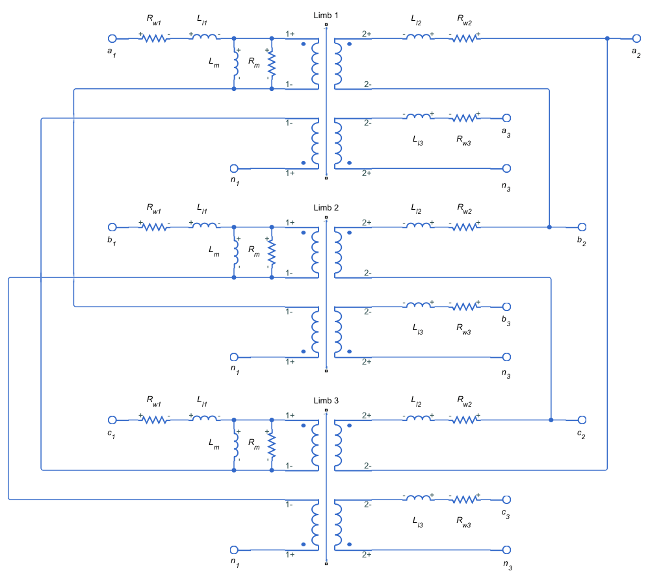
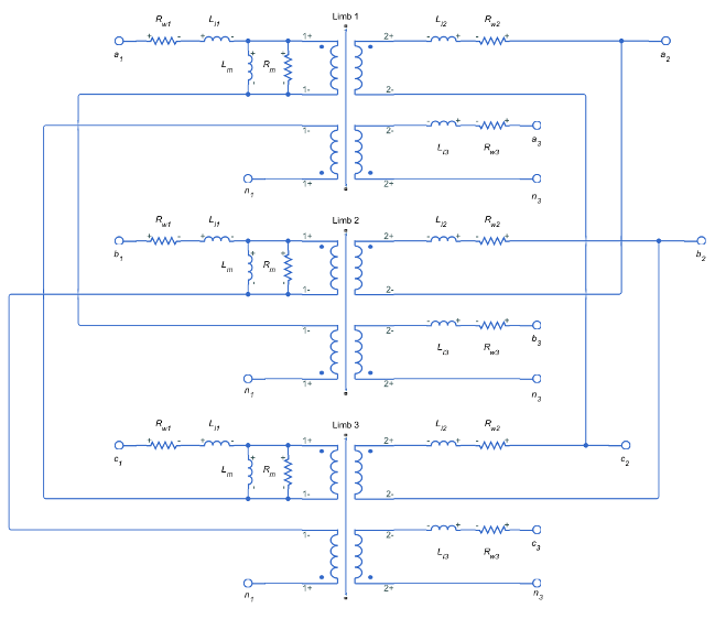
In these diagrams:

  • Rw1 is the primary winding resistance.

  • Ll1 is the primary leakage reactance.

  • Rw2 is the delta secondary winding resistance.

  • Ll2 is the delta secondary leakage reactance.

  • Rw3 is the wye secondary winding resistance.

  • Ll3 is the wye secondary leakage reactance.

  • Rm is the shunt magnetizing resistance.

  • Lm is the shunt magnetizing reactance.

Variables

Use the Variables settings to specify the priority and initial target values for the block variables before simulation. For more information, see Set Priority and Initial Target for Block Variables.

To enable the Wye secondary currents variable, set Secondary connection to Wye or Wye and Delta.

To enable the Delta secondary currents variable, set Secondary connection to Delta or Wye and Delta.

Ports

Conserving

expand all

Expandable three-phase electrical conserving port associated with the three-phase, [a1 b1 c1], voltage of the primary winding.

Expandable three-phase electrical conserving port associated with the three-phase, [a2 b2 c2], voltage of the first secondary winding.

Dependencies

To enable this port, set Secondary connection to Delta or Wye and Delta.

Expandable three-phase electrical conserving port associated with the three-phase, [a3 b3 c3], voltage of the second secondary winding.

Dependencies

To enable this port, set Secondary connection to Wye or Wye and Delta.

Electrical conserving port associated with the wye secondary winding neutral point.

Electrical conserving port associated with the interconnection of the zigzag winding.

Dependencies

To enable this port, set Zigzag configuration to Accessible winding interconnects.

Parameters

expand all

Whether to model composite or expanded three-phase ports.

Composite three-phase ports represent three individual electrical conserving ports with a single block port. You can use composite three-phase ports to build models that correspond to single-line diagrams of three-phase electrical systems.

Expanded three-phase ports represent the individual phases of a three-phase system using three separate electrical conserving ports.

Main

Apparent power flowing through the transformer when operating at rated capacity, in V*A.

Rated or nominal frequency of the AC network to which the transformer is connected, in Hz. The value must be greater than 0.

RMS line voltage applied to the primary winding under normal operating conditions, in V. The value must be greater than 0.

Configuration of zigzag winding.

Configuration of the secondary connection.

Type of delta connection.

Dependencies

To enable this parameter, set Secondary connection to Delta or Wye and Delta.

RMS line voltage applied to the delta secondary winding under normal operating conditions, in V. The value must be greater than 0.

Dependencies

To enable this parameter, set Secondary connection to Delta or Wye and Delta.

RMS line voltage applied to the wye secondary winding under normal operating conditions, in V. The value must be greater than 0.

Dependencies

To enable this parameter, set Secondary connection to Wye or Wye and Delta.

Phase offset between the zigzag and the secondary windings.

Impedances

Per-unit power loss in the primary winding. The value must be greater than 0.

Per-unit power loss in the delta secondary winding. The value must be greater than 0.

Dependencies

To enable this parameter, set Secondary connection to Delta or Wye and Delta.

Per-unit power loss in the wye secondary winding. The value must be greater than 0.

Dependencies

To enable this parameter, set Secondary connection to Wye or Wye and Delta.

Whether to model magnetic flux losses.

Per-unit magnetic flux loss in the primary winding. The value must be greater than 0.

Dependencies

To enable this parameter, set Leakage reactance to Include.

Per-unit magnetic flux loss in the delta secondary winding. The value must be greater than 0.

Dependencies

To enable this parameter, set Leakage reactance to Include and Secondary connection to either Delta or Wye and Delta.

Per-unit magnetic flux loss in the wye secondary winding. The value must be greater than 0.

Dependencies

To enable this parameter, set Leakage reactance to Include and Secondary connection to either Wye or Wye and Delta.

Whether to model the transformer core losses.

Per-unit losses in the transformer core. The value must be greater than 0.

Dependencies

To enable this parameter, set Magnetizing resistance to Include.

Whether to model magnetic effects of the transformer core.

Whether to represent magnetic saturation.

Dependencies

To enable this parameter, set Magnetizing reactance to Include.

Per unit vector of currents. The first value must be 0. This parameter must be strictly ascending.

Dependencies

To enable this parameter, set Magnetizing reactance to Include and Magnetic saturation representation to Lookup table (phi versus i).

Per unit vector of magnetic flux. The first value must be 0. This parameter must be strictly ascending.

Dependencies

To enable this parameter, set Magnetizing reactance to Include and Magnetic saturation representation to Lookup table (phi versus i).

Per-unit magnetic effects of the transformer core when operating in its linear region. The value must be greater than 0.

Dependencies

To enable this parameter, set Magnetizing reactance to Include and Magnetic saturation representation to None.

Extended Capabilities

C/C++ Code Generation
Generate C and C++ code using Simulink® Coder™.

Version History

Introduced in R2019b