Main Content

Transmission Line (Three-Phase)

Three-phase transmission line using lumped-parameter pi-section line model

  • Transmission Line (Three-Phase) block

Libraries:
Simscape / Electrical / Passive / Lines

Description

The Transmission Line (Three-Phase) block models a three-phase transmission line using the lumped-parameter pi-line model. This model takes into account phase resistance, phase self-inductance, line-line mutual inductance and resistance, line-line capacitance, and line-ground capacitance.

To simplify the block-defining equations, Clarke’s transformation is used. The resulting equations are:

V1V2=[R+2RmRRmRRm]I1+[L+2MLMLM]dI1dt

I1+I2=[CgCg+3ClCg+3Cl]dV2dt

I1=TI1

I2=TI2

V1=TV1

V2=TV2

T=13[1201123211232]

where:

  • R is the line resistance for the segment.

  • Rm is the mutual resistance for the segment.

  • L is the line inductance for the segment.

  • M is the value of the Mutual inductance parameter.

  • Cg is the line-ground capacitance for the segment.

  • Cl is the line-line capacitance for the segment.

  • T is the Clarke’s transformation matrix.

  • I1 is the three-phase current flowing into the ~1 port.

  • I2 is the three-phase current flowing into the ~2 port.

  • V1 is the three-phase voltage at the ~1 port.

  • V2 is the three-phase voltage at the ~2 port.

The positive and zero-sequence parameters are defined by the diagonal terms in the transformed equations:

R0=R+2Rm

R1=RRm

L0=L+2M

L1=LM

C0=Cg

C1=Cg+3Cl

Rearranging these equations gives the physical line quantities in terms of positive and zero-sequence parameters:

R=2R1+R03

Rm=R0R13

L=2L1+L03

M=L0L13

Cl=C1C03

Cg=C0

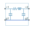
The figure shows the equivalent electrical circuit for a single-segment pi-line model using Clarke’s transformation.

To increase fidelity, you can use the Number of segments parameter to repeat the pi-section N times, resulting in an N-segment transmission line model. More segments significantly slows down your simulation.

To improve numerical performance, you can add parasitic resistance and conductance components. Choosing large values for these components improves simulation speed but decreases simulation accuracy.

Propagation Speeds

The Transmission Line (Three-Phase) calculates the positive-sequence propagation speeds by using these equations:

  • Z1=R1+jωL1 is the series impedance, in Ω/Km.

  • Y1=jωC1 is the shunt admittance, in s/Km.

  • γ1=Z1Y1 is the propagation constant.

  • ν1=ωImag(γ1) is the propagation speed, in Km/s, where ω=2πf.

For zero-sequence propagation speed, the equations are the same but R1, L1, C1, Z1, Y1, γ1, and ν1 are R0, L0, C0, Z0, Y0, γ0, and ν0.

Faults

The Transmission Line (Three-Phase) block allows you to model these types of faults at specific position along the transmission line:

  • Single-phase-to-ground fault (a-g, b-g, or c-g)

  • Two-phase fault (a-b, b-c, or c-a)

  • Two-phase-to-ground fault (a-b-g, b-c-g, or c-a-g)

  • Three-phase fault (a-b-c)

  • Three-phase-to-ground fault (a-b-c-g)

An input physical signal, F, triggers the fault. If the input physical signal is greater than or equal to 0.5, the fault is active. If the input physical signal is less than 0.5, the fault is inactive.

Ports

Input

expand all

Physical signal port associated with the fault control signal.

Dependencies

To enable this port, set Enable fault to Yes

Conserving

expand all

Expandable three-phase port.

Expandable three-phase port.

Electrical conserving port corresponding to ground connection at ~1 end of the transmission line.

Electrical conserving port corresponding to ground connection at ~2 end of the transmission line.

Electrical conserving port corresponding to ground connection at fault position 1.

Dependencies

To enable this port, set Accessible ground connections at fault position to Yes

Electrical conserving port corresponding to ground connection at fault position 2.

Dependencies

To enable this port, set Accessible ground connections at fault position to Yes

Parameters

expand all

Whether to model composite or expanded three-phase ports.

Composite three-phase ports represent three individual electrical conserving ports with a single block port. You can use composite three-phase ports to build models that correspond to single-line diagrams of three-phase electrical systems.

Expanded three-phase ports represent the individual phases of a three-phase system using three separate electrical conserving ports.

Main

Length of the transmission line.

Frequency used for the R, L, C, G specification, where:

  • R is line resistance per unit length.

  • L is the line inductance per unit length.

  • C is the line capacitance per unit length.

  • G is the line conductance per unit length.

Resistance of the transmission line per phase per-unit length.

Self-inductance of the transmission line per phase per-unit length.

Line-line mutual inductance per-unit length. Set this to 0 to remove mutual inductance.

Line-line capacitance per-unit length.

Line-ground capacitance per-unit length. The default value is 0μF/km (no line-ground capacitance).

Line-line mutual resistance per unit length. The default value is 0Ohm/km (no line-line mutual resistance).

Number of segments in the pi-line model.

Parasitics

Resistance value, divided by the number of segments, that is added in series with every capacitor in the model.

Conductance value, divided by the number of segments, that is added in parallel with every series resistor and inductor in the model.

Faults

Whether to enable faults.

Type of fault to model. The visibility of related parameters depends on the fault model. Options are:

  • Single-phase to ground (a-g)

  • Single-phase to ground (b-g)

  • Single-phase to ground (c-g)

  • Two-phase (a-b)

  • Two-phase (b-c)

  • Two-phase (c-a)

  • Two-phase to ground (a-b-g)

  • Two-phase to ground (b-c-g)

  • Two-phase to ground (c-a-g)

  • Three-phase (a-b-c)

  • Three-phase to ground (a-b-c-g)

Resistance between the phase connection and the neutral point when the fault is active.

Dependencies

To enable this parameter set the Fault type parameter to:

  • Single-phase to ground (a-g)

  • Single-phase to ground (b-g)

  • Single-phase to ground (c-g)

  • Two-phase (a-b)

  • Two-phase (b-c)

  • Two-phase (c-a)

  • Two-phase to ground (a-b-g)

  • Two-phase to ground (b-c-g)

  • Two-phase to ground (c-a-g)

  • Three-phase (a-b-c)

  • Three-phase to ground (a-b-c-g)

Resistance between the neutral point and the electrical reference when fault is active.

Dependencies

To enable this parameter set the Fault type parameter to:

  • Single-phase to ground (a-g)

  • Single-phase to ground (b-g)

  • Single-phase to ground (c-g)

  • Two-phase to ground (a-b-g)

  • Two-phase to ground (b-c-g)

  • Two-phase to ground (c-a-g)

  • Three-phase to ground (a-b-c-g)

Conductance between the phase connection and the neutral point when the fault is not active.

Dependencies

To enable this parameter set the Fault type parameter to:

  • Single-phase to ground (a-g)

  • Single-phase to ground (b-g)

  • Single-phase to ground (c-g)

  • Two-phase (a-b)

  • Two-phase (b-c)

  • Two-phase (c-a)

  • Two-phase to ground (a-b-g)

  • Two-phase to ground (b-c-g)

  • Two-phase to ground (c-a-g)

  • Three-phase (a-b-c)

  • Three-phase to ground (a-b-c-g)

Location where the fault occurs

Dependencies

To enable this parameter set Enable fault to Yes.

Number of segments in the pi-line model before the fault occurs

Dependencies

To enable this parameter set Enable fault to Yes.

Select Yes to access the ground connections at the fault position, otherwise the ground connections at the fault position are connected to the electrical reference internally

Dependencies

To enable this parameter set Enable fault to Yes.

Extended Capabilities

C/C++ Code Generation
Generate C and C++ code using Simulink® Coder™.

Version History

Introduced in R2013b