AC6 - PM Synchronous 3HP Motor Drive
This example shows the AC6 PM Synchronous Motor Drive during speed regulation.
H.Blanchette, L.-A. Dessaint (Ecole de technologie superieure, Montreal)
Description
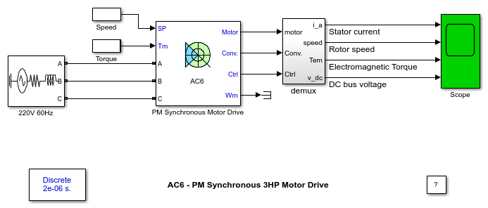
This circuit uses the AC6 block of Specialized Power Systems library. It models a permanent magnet (PM) synchronous motor drive with a braking chopper for a 3HP motor.
The PM synchronous motor is fed by a PWM voltage source inverter, which is built using a Universal Bridge Block. The speed control loop uses a PI regulator to produce the flux and torque references for the vector control block. The vector control block computes the three reference motor line currents corresponding to the flux and torque references and then feeds the motor with these currents using a three-phase current regulator.
Motor current, speed, and torque signals are available at the output of the block.
Simulation
Start the simulation. You can observe the motor stator current, the rotor speed, the electromagnetic torque and the DC bus voltage on the scope. The speed set point and the torque set point are also shown.
At time t = 0 s, the speed set point is 300 rpm. Observe that the speed follows precisely the acceleration ramp.
At t = 0.5 s, the full load torque is applied to the motor. You can observe a small disturbance in the motor speed, which stabilizes very quickly.
At t = 1 s, the speed set point is changed to 0 rpm. The speed decreases down to 0 rpm following precisely the deceleration ramp.
At t = 1.5 s., the mechanical load passes from 11 Nm to -11 Nm. The motor speed stabilizes very quickly after a small overshoot.
Finally, note how well the DC bus voltage is regulated during the whole simulation period.
Notes
1) The power system has been discretised with a 2 us time step. The speed controller uses a 140 us sample and the vector controller uses a 20 us sample time in order to simulate a microcontroller control device.
2) A simplified version of the model using average-value inverter can be used by selecting 'Average' in the 'Model detail level' menu of the graphical user-interface. The time step can then be increased up to 75 us. This can be done by typing 'Ts = 75e-6' in the workspace, by setting Vector control sample time to 75e-6 and by setting Speed controller sample time to 150e-6 in the case of this example. See also ac6_example_simplified model.
You can also select a web site from the following list:
Americas
- América Latina (Español)
- Canada (English)
- United States (English)
Europe
- Belgium (English)
- Denmark (English)
- Deutschland (Deutsch)
- España (Español)
- Finland (English)
- France (Français)
- Ireland (English)
- Italia (Italiano)
- Luxembourg (English)
- Netherlands (English)
- Norway (English)
- Österreich (Deutsch)
- Portugal (English)
- Sweden (English)
- Switzerland
- United Kingdom (English)