Push-Pull Buck Converter in Continuous Conduction Mode
This example shows how to control the output voltage of a push-pull buck converter. The current flowing through the inductor is never zero. The DC-DC converter therefore operates in continuous conduction mode (CCM). To convert and maintain the nominal output voltage, the PI Controller subsystem uses a simple integral control. During startup, the reference voltage ramps up to the desired output voltage.
The converter operates in CCM only if
 ,
,
where:
 .
.
 .
.
 is the filter inductance.
 is the load resistance.
 is the switching period for each MOSFET. That is,
  , where
  is the switching frequency.
 is the duty cycle of PWM input to the gate of each MOSFET. That is,
  , where
  is the ON time of the MOSFET.
Open Model

Specify the Design Parameters
The system is required to generate and maintain an output voltage of 80 V with a full load power capability of 1000 W. The input voltage is 400 V and the transformer turns ratio is 2. The full load includes a constant load and a cyclic load. The 'PushPullBuckCCMData.m' script defines the design parameters as variables in the MATLAB® workspace.
Calculate the Open-Loop Duty Cycle
The duty cycle depends on the input voltage, the turns ratio and the desired output voltage.
Determine the Constant Load Resistance
Calculate the Filter Inductance
Choose the inductance value based on the input and output specifications of the converter. The inductance value depends on the input and output specifications of the converter. For this example, the converter is required to work in CCM for 20-100% of full load power. When, at the lower boundary condition, the power is 20% of full load power, the average load current is 20% of full load average current, I_fl_average. At the end of each cycle at the lower boundary condition, the inductor current goes to zero. The inductor ripple current, del_I, at this point is twice the average output load current, that is 40% of the full load average output current.
Plot Inductance Versus Inductor Current Ripple
Generate this plot to see how the filter inductance relates to the inductor ripple current (expressed as a percentage of full load current). For this example, the marker at 40% corresponds to an inductance of 1.2e-04 H.

Choose a Filter Capacitance
Plot Capacitance Versus Voltage Ripple
Generate this plot to see how capacitance for limiting the output voltage ripple varies depending on the design parameters. For this example, the marker at 1% Output Voltage Ripple corresponds to a capacitance of 9.766e-06 F.

Run the Simulation
View Simulation Results
To view summary results during or after the simulation, open the Circuit Scope block from the model window or, at the MATLAB command prompt, enter open_system('PushPullBuckCCM/Scopes/Circuit Scope');.

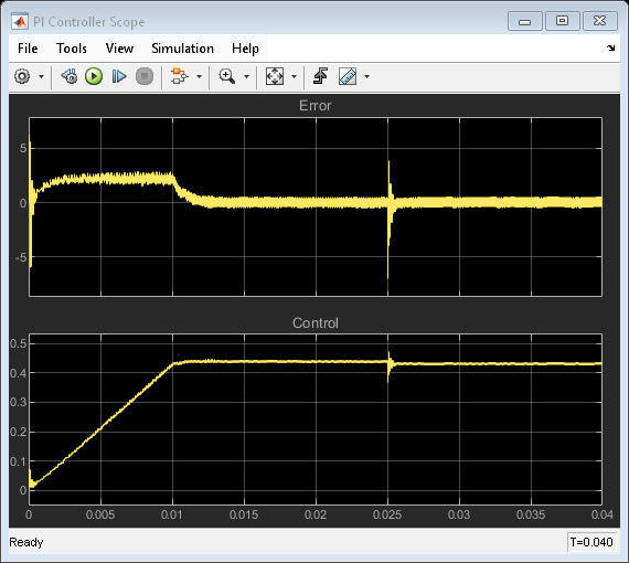
To view the control and error data during or after the simulation, open the PI Controller Scope block from the model window or enter open_system('PushPullBuckCCM/Scopes/PI Controller Scope');.
After the simulation, to view logged Simscape™ data using the Simscape Results Explorer, enter sscexplore(simlog_PushPullBuckCCM);.