Monitor Accelerometer Data Using Gauges on Android
This example shows how to deploy gauges on an Android® device by using Simulink® Support Package for Android Devices. The Simulink model used in this example showcases the visualization capabilities of the Gauge and Half Gauge blocks. On deployment, the support package generates a standalone application with three gauges that monitor the accelerometer data along the three axes of the device in real-time.
Copyright(C) 2020-2023 The MathWorks, Inc.
Prerequisite
Before you start this example, complete the Getting Started with Android Devices example.
Required Hardware
Android device
USB cable
Model Description
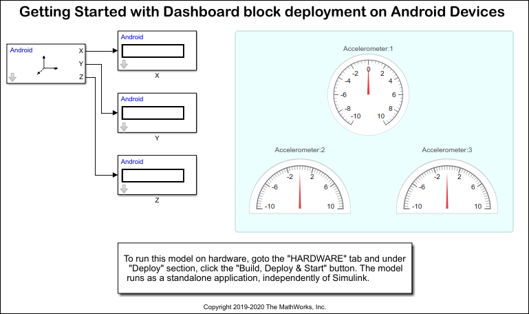
The Accelerometer block measures acceleration along the x-, y-, and z- axes of an Android device. To visualize the accelerometer data effectively, the output of the Accelerometer block is connected to the Gauge and Half Gauge blocks.
The Gauge block, Accelerometer:1, is connected to the X output port of the Accelerometer block. The two Half Gauge blocks, Accelerometer:2 and Accelerometer:3, are connected to the Y and Z output ports of the Accelerometer block. You can modify the range of the Accelerometer:1, Accelerometer:2, and Accelerometer:3 blocks to fit your requirement. The tick intervals and the color code specified for in-specification and out-of-specification ranges are not reflected in the deployed model.
The support package deploys only blocks placed inside a Dashboard panel. Any block outside the panel is not deployed. Every panel is deployed as a separate tab on the device screen. In this example, as the Accelerometer:1, Accelerometer:2, and Accelerometer:3 blocks are placed inside a panel, only these blocks are deployed. If you have multiple panels in a model, the support package creates multiple tabs. You can navigate between the sibling tabs with a swipe.
Open the androidAccelDashboard Simulink model.
Step 1: Configure Acceleration Dashboard Model
1. Open the androidAccelDashboard Simulink model.
2. On the Modeling tab, click Model Settings to open the Configuration Parameters dialog box.
3. In the Configuration Parameters dialog box, select Hardware Implementation. Verify that the Hardware board parameter is set to Android Device.
4. Go to Hardware board settings > Target hardware resources > Groups and select Device options.
5. From the Device list, select your Android device. If your device is not listed, click Refresh.
Note: If your device is not listed even after clicking Refresh, ensure that you have enabled the USB debugging option on your device. To enable USB debugging, enter androidhwsetup in the MATLAB® Command Window and follow the onscreen instructions.
6. Under Target hardware resources, select the UI generation properties. Set the Generated UI layout on device to be Fit to Screen. This option rescales the size of the user interface (UI) components to fit the screen size of your device.
Step 2: Monitor Acceleration on Android Device
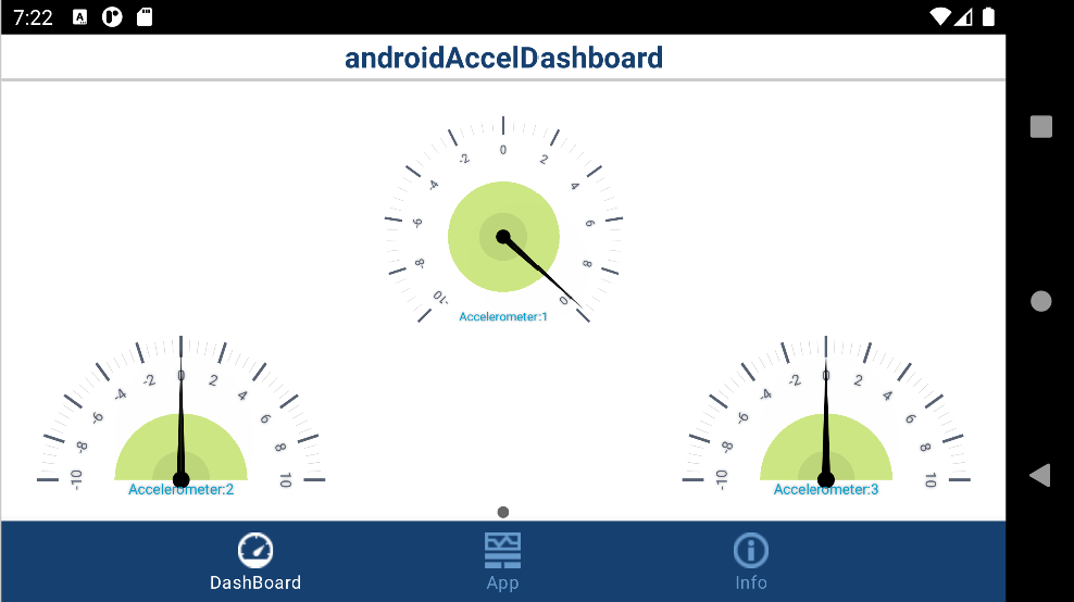
1. On the Hardware tab of the androidAccelDashboard Simulink model, in the Mode section, select Run on board and then click Build, Deploy & Start. This action builds, downloads, and runs the model as a standalone application on the Android device. The application continues to run even if the device is disconnected from the computer. The UI of the application contains three gauges on the Dashboard tab of the device. The gauges represent acceleration along the x-, y-, and z- axes of the device.
Note: Even after successful deployment, if a gauge does not appear on the device screen, ensure that:
The Gauge block is placed inside the Dashboard panel.
The size of the Gauge block is less than twice the size of the device screen.
2. Hold the device in different positions and observe the readings on the gauges.
Step 3: Add Swipe Views to Acceleration Dashboard Model
A premodified model, androidAccelDashboard_modified, is already available for you to use. If you choose to use the modified model, skip these steps.
1. In the androidAccelDashboard_modified Simulink model, select the panel containing gauge blocks.
2. Click the ellipsis that appears at the top of the panel. Select Edit Panel from the menu that appears.
3. Drag Accelerometer:2 and Accelerometer:3 out of the panel.
4. Select the panel and click the Done Editing button that appears at the top of the panel.
5. Select Accelerometer:2. From the ellipsis that appears, select Promote to Panel. Accelerometer:2 moves from canvas into the panel.
6. Enter the edit mode and then drag Accelerometer:3 inside the newly created panel.
Open the androidAccelDashboard_modified Simulink model.

7. On the Hardware tab of the Simulink model, in the Mode section, select Run on board and then click Build, Deploy & Start. Wait for the model to be fully deployed. The application now contains two tabs. The gauge in the first tab displays acceleration along the x- axis. The gauges in the second tab display acceleration along the y- and z- axes of the device. You can switch between these tabs with a swipe.


See Also
Select a Web Site
Choose a web site to get translated content where available and see local events and offers. Based on your location, we recommend that you select: United States.
You can also select a web site from the following list
Americas
- América Latina (Español)
- Canada (English)
- United States (English)
Europe
- Belgium (English)
- Denmark (English)
- Deutschland (Deutsch)
- España (Español)
- Finland (English)
- France (Français)
- Ireland (English)
- Italia (Italiano)
- Luxembourg (English)
- Netherlands (English)
- Norway (English)
- Österreich (Deutsch)
- Portugal (English)
- Sweden (English)
- Switzerland
- United Kingdom (English)