Surround Sound Matrix Encoding
This example shows how to generate a stereo signal from a multichannel audio signal using matrix encoder from the Simulink® Support Package for Android® Devices.
Matrix encoding is an audio technique that transforms N-channel signals to M-channel signals, where N > M.
Matrix encoding enables the same audio content to be played on different systems. For example, a surround sound multichannel signal can be encoded into a stereo signal using a matrix encoder. The stereo signal can then be played on a system without surround sound capabilities.
In this example, we showcase a matrix encoder used to encode a four-channel signal (left, right, center, and surround) to a stereo signal.
Required Hardware
Android device
Headphones
USB cable
Task 1 - Connect the Android Device
Before you start this example, we recommend that you complete the Getting Started with Android Devices.
1. Connect the Android device to your computer using the USB cable.
2. Connect a pair of headphones to the headphone jack of the device.
3. Using the Hardware Setup screen, configure the Android network.
Task 2 - Open Matrix Encoding Simulink Model
Open the androidMatrixEncoding Simulink model.

The Audio Matrix Encoding model consists of three components: the Audio Channels subsystem, the Matrix Encoder subsystem, and the Audio Playback block.
The input to the Matrix Encoder consists of four separate audio channels (center, left, right, and surround).
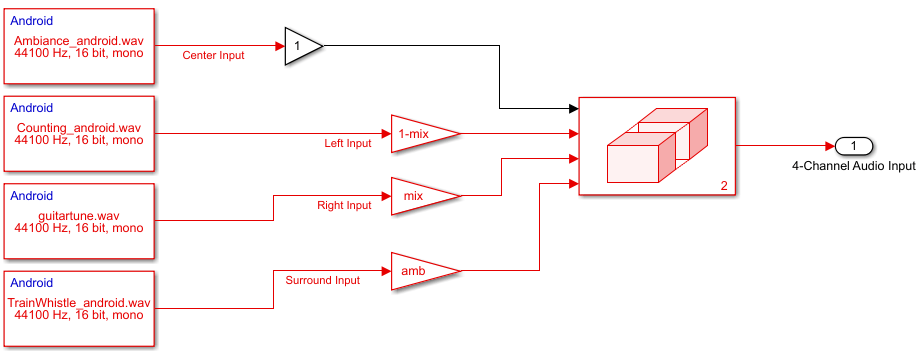
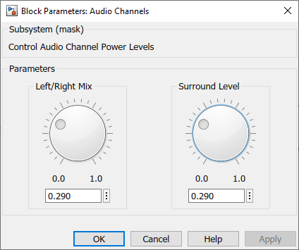
Double-click the Audio Channels subsystem to launch a tuning dialog box. The dialog box enables you to control the relative power levels between the right channel and left channel inputs, as well as the power level of the surround channel.
Matrix Encoder
The Matrix Encoder encodes the four input channels into a stereo signal.

Because the input left and right channels only contribute to the output left and right channels, respectively, the output stereo signal conserves the balance between left and right channels.
The surround input channel is passed through a Hilbert transformer, thereby creating a 180 degree phase differential between the surround components feeding the left and right stereo outputs. The encoding scheme used here is a simplified version of the scheme used in the Dolby Pro Logic Surround Decoder [1].
Audio Output
The Audio Playback block plays the converted stereo audio on the speaker of the device.
Task 3 - Configure the Matrix Encoder Simulink Model
1. Go to Modeling tab and press Ctrl+E to open the Configuration Parameters dialog box.
2. In the Configuration Parameters dialog box, navigate to Hardware Implementation > Hardware board and select Android Device.
3. Go to Hardware board settings > Target hardware resources > Groups and select Device options.
4. From the Device list, select your Android device. If your device is not listed, click Refresh.
Note: If your device is not listed even after clicking Refresh, ensure that you have enabled the USB debugging option on your device. To enable USB debugging, enter androidhwsetup in the MATLAB® Command Window and follow the onscreen instructions.
5. Click Apply. Click OK to save your changes.
Task 4 - Monitor and Tune the Simulink Model
1. On the Hardware tab of the Simulink model, in the Mode section, select Run on board and then click Monitor & Tune. The lower-left corner of the model window displays status as the support package generates the code. After successfully generating the code, the support package loads and runs the code on the hardware.
2. Double-click the Audio Channels block and tune the Left/Right Mix and Surround Level parameters to control the power of the right, left, and surround channels.
References
[1] Dolby Pro Logic Surround Decoder: Principles of Operation, Roger Dressler, Dolby Labs
Select a Web Site
Choose a web site to get translated content where available and see local events and offers. Based on your location, we recommend that you select: United States.
You can also select a web site from the following list
Americas
- América Latina (Español)
- Canada (English)
- United States (English)
Europe
- Belgium (English)
- Denmark (English)
- Deutschland (Deutsch)
- España (Español)
- Finland (English)
- France (Français)
- Ireland (English)
- Italia (Italiano)
- Luxembourg (English)
- Netherlands (English)
- Norway (English)
- Österreich (Deutsch)
- Portugal (English)
- Sweden (English)
- Switzerland
- United Kingdom (English)