Integrate Software Components into Compositions Using Software Component Designer
R2026bAfter you create and configure individual software component models in Simulink®, you can compose them into a software architecture model to define system-level interactions and validate component connectivity. Composing components into an architecture allows you to:
View and refine QoS properties at the architecture level without opening individual component models
Validate that connected components have compatible communication configurations
Simulate the full composition with a mock run-time environment
This topic assumes you have software component models with interfaces and QoS properties already configured. If you have not yet created software component models, see Create Software Component Models in Simulink.
To create a software architecture model, from a Simulink model, on the Simulation tab, select New > Architecture
 . System Composer™ opens a new empty software architecture model. For more information about
architecture models, see Author Software Architectures.
. System Composer™ opens a new empty software architecture model. For more information about
architecture models, see Author Software Architectures.
Add Software Components to Software Architecture
Add software components to the architecture to represent the elements of a software composition.
You can create software components in the architecture using one of these methods:
Draw components. Click and drag on the canvas to draw a rectangle. Release the mouse button to display the component outline, and select the Software Component option.
Use the palette. Click and drag a component from the palette, and release the component onto the canvas.
To associate components within the architecture to their Simulink behavior, link components to existing software component models.
Right-click a software component on the canvas. Select Link to Model.
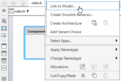
Enter or browse for the name of the software component model you want to link.

Click OK.
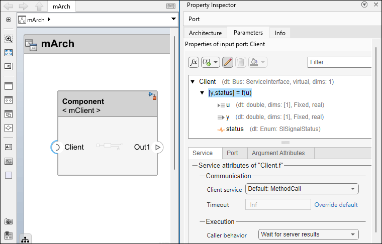
The Simulink icon indicates that the component is now linked to a Simulink model.
You can configure and modify quality of service (QoS) properties at the architecture level, which allows you to refine communication and execution behavior for the software composition without opening each individual software component model. For more information, see Configure Communication and Execution Behavior of Software Components.
Note
To remove a linked behavior from a reference component while preserving
communication and execution properties on its port elements, select the
component and, on the toolstrip, click Modeling > Component > Inline Linked Model. You can also use the
inlineComponent function. For more information, see Remove Component Behavior and Preserve Quality of Service Properties.
Connect Software Components and Validate Connections
You can connect components in the architecture to represent component-to-component interactions. Connections between components reflect data and service interactions defined by the interfaces on the component ports.
To connect components, select a port and drag a line to another port on the canvas.
You can validate connectivity of components during edit-time at the architecture level.
On the Software Component tab, in the
Design section, click Validate
Connections
 . The software checks whether the QoS properties
of the port elements are compatible.
. The software checks whether the QoS properties
of the port elements are compatible.
Validation Checks
| Connection Type | Validation Check | Description |
|---|---|---|
| Send-Receive | Communication Services Consistency | Input and output port elements of send-receive connections must be configured with the same communication service. Sender service and Receiver service parameter values of data elements must match. |
| Complex Data Type Not Supported | In the signal attributes of data elements, the
Complexity parameter value must be
set to | |
| Client-Server | Function Prototype Consistency | Function elements of connected client and server ports must be configured with compatible interfaces. The number and names of input and output arguments must match. |
| Mapped Function Element of Client Port | Client ports must be connected to a server port that includes all required function elements. For
example, if a client port has two functions: | |
| Any | Deployment Property Consistency | Connected components must use the same middleware protocol (DDS or SOME/IP), and their associated deployment properties must match. |
After connection validation, you can simulate the software composition to evaluate interactions between components and verify system-level behavior. For more information, see Simulate Software Architectures to Validate Run-time Behavior.

