Configure Communication and Execution Behavior of Software Components
R2026bAfter you define interfaces and assign them to component ports, you configure communication and execution behavior using quality of service (QoS) properties on port elements. QoS properties configure run-time communication and execution behavior for component ports, including:
Send-receive communication semantics, such as buffering semantics, queue capacity, and initial values
Client-server interaction behavior, including timeouts, caller behavior, and handling of delayed or missing responses
Execution triggering, such as time‑based execution or data‑triggered execution on data arrival
Communication error reporting, using status elements or status arguments to handle errors that the middleware reports
These settings define how components exchange data and services and how the system coordinates execution at run time, without changing the functional behavior that the component implements.
In this topic, you configure communication and execution behavior and error handling for send-receive and client-server interactions, and data‑triggered execution.
Configure Send-Receive Communication Behavior
Send-receive communication defines the run-time buffering and access semantics for data exchanged between components. You configure these semantics by setting communication properties on data elements of input and output ports.
By default, send-receive communication uses first-in-first-out (FIFO) queuing, where the receiver reads values in the order in which the queue received them. Communication properties control aspects of this behavior, such as queue capacity and the initial value returned when the queue is empty.
Configure Input Data Elements
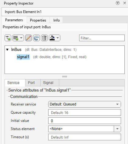
To configure communication properties for a send-receive data element, open the Property Inspector and, on the Parameters tab, select a data element. Then on the Service tab, use the Communication section to set these properties.
Receiver service – Selects how the receiver accesses buffered data. Set to
Queuedto read values from a queue. Set toLatestValueto read only the most recent value.Queue capacity – Sets the maximum number of values stored in the queue, with a default value of
16.Initial value – Defines the value used by the receiver before it receives the first valid value from the sender, with a default value of
0.Status element – Optional element that enables run-time reporting of data access status.
Timeout – Specifies maximum time allowed since valid data was last received by the port, with a default value of
Inf. Set to a finite value to enable timeout monitoring.
Configure Output Data Elements
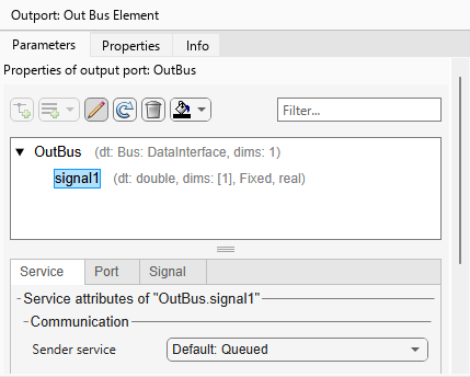
Sender properties must be compatible with the receive semantics that connected components expect. For output port data elements, set Sender service to match the intended receiver behavior:
Use
Queuedto match receivers using FIFO buffering and read queued data.Use
LatestValueto match receivers that read only the most recent value.
Tip
To prepare for validation of component behavior, log input, output, and status signals so you can view results in the Simulation Data Inspector.
Handle Communication Errors with Status Elements
Software components often need to detect and react to communication failures.
Communication error handling defines run-time error‑reporting semantics for data and
service interactions. To model communication errors in a platform-independent way, use
status values based on the predefined enumerated data type,
SlSignalStatus.
You can use status values in send-receive and client-server communication.
Send-receive – Add a status element for a received data element.
Client-server – Use the optional status argument of a function call.
This table explains each SlSignalStatus
error code.
SlSignalStatus | Description |
|---|---|
OK | No errors occurred. This status usually means the component received new data. |
TIMEOUT | The component did not receive a response within the configured timeout
period. Timeout occurs T seconds after the caller sends
the call. Status remains TIMEOUT until the component
receives a new return value. |
COM_NOT_AVAILABLE | The software detected a communication link failure. Indicates that the
middleware cannot deliver data (for example, server unavailable, broken
link, unconnected port, or component not started). Status remains
COM_NOT_AVAILABLE until the component receives a new
return value. |
The OK status does not always indicate that new data was
received. For send-receive communication, SlSignalStatus.OK is returned when
reading from an empty queue, in which case the initial value is used. For client-server
communication, SlSignalStatus.OK is returned when the server result is not
yet ready, in which case the previous value is returned. To distinguish between fresh data and a
fallback value, use a status element to track data freshness.
To create a status element for a data element, select the data element and use one of these methods:
From the canvas, hold Ctrl while you drag an existing bus element block. When you release the pointer, click New Status Element.
From the Property Inspector, in the Status element list, select
<Add Status Element>.From the Property Inspector toolstrip, expand Add element
 and select
 Add Status element for selection.
The newly created status element appears with a status icon  .
.
To trace data elements to their ports and associated status elements, select a data element in the Property Inspector or a bus element on the canvas.
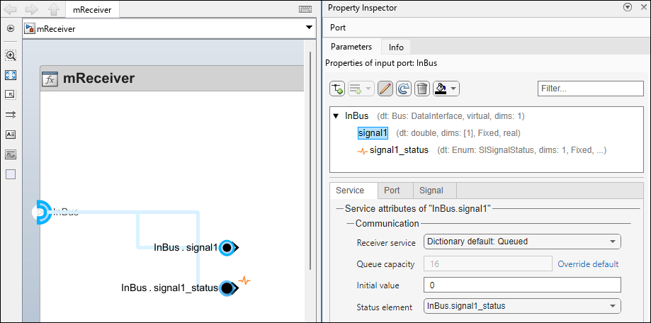
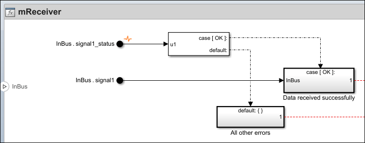
You can implement conditional algorithms to handle status conditions. For example, here are two possible approaches to handling errors:
Compare a status value to
SlSignalStatus.OKusing a Constant block and a Relational Operator block.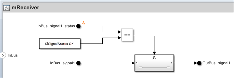
Use Switch Case and Switch Case Action Subsystem blocks to branch on status values.
Configure Client-Server Communication Behavior
Client-server communication properties define how function calls are issued, scheduled, and completed at run-time between client and server components.
To configure client-server communication and execution behavior, select a function element in the Property Inspector and use the Service tab.
The Property Inspector displays a toolbar when you select a client or server port. Use the toolbar buttons to manage function elements and arguments:
Add Function Element — Add a function element to the port (disabled when a service interface is attached).
Add Argument — Add an input, output, in-out, or status argument to the selected function element.
Refresh — Reload the Parameters tab of the Property Inspector.
Remove — Remove selected function elements or arguments.
Set Color — Set the display color of the selected port.
When you select a function element in the Parameters tab, the Service tab displays its communication and execution properties.
When you select an argument in the Parameters tab, the Attributes panel displays the argument attributes.
Configure Server Function Elements
Map each server function element to a scoped Simulink® function that implements the operation.
Create or select a Simulink Function block that matches the function element prototype.
In the Property Inspector, on the Service tab, in the Execution section, set Simulink function to the corresponding scoped Simulink Function block.
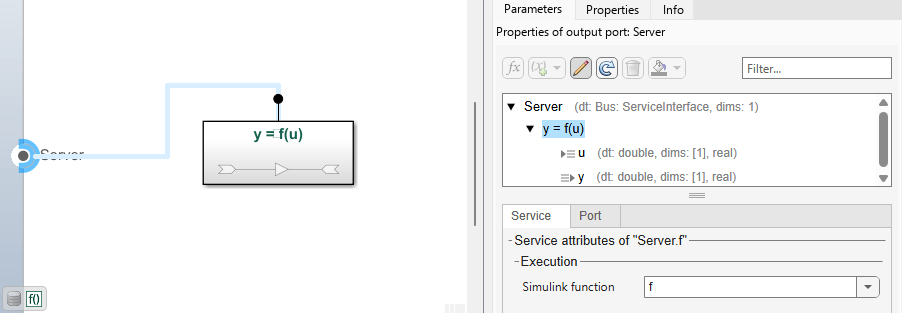
After mapping, implement the function algorithm inside the Simulink Function subsystem. ArgIn and ArgOut blocks represent input and output arguments.
Configure Client Function Elements
Configure client communication timing and execution behavior on each client function element.
In the Property Inspector, on the Service tab, in the Communication section, set properties that control whether the client can request a response from the server and how middleware responses are handled.
Timeout – Specifies maximum time allowed between when the client invokes a function and receives results, with a default value of
Inf. Set to a finite value to enable timeout monitoring.Server response not required – Specifies whether the client requires a response from the server, with a default value of
off.The Server response not required property can be selected only for function elements whose function prototype defines no output arguments. When this property is selected, the Caller behavior execution property is read-only and ignored by the software as the client does not receive a response from the server. To clear the Server response not required property, select the function element in the Interface Editor, and then edit its properties in the Property Inspector.
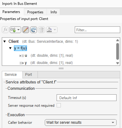
In the Execution section, set Caller behavior to define how the client proceeds while waiting for results.
Wait for server results– The client blocks execution until results become available within the same step, which requires the Timeout value to be less than or equal to the step size.Allow delayed server results– The client continues execution and polls for results across multiple steps, up to the configured Timeout duration.
Map each client function element to a Function Caller block and set the Function prototype parameter to match the interface. For example, if the Simulink function prototype is y = f(u) and the client port is named Client, the Function prototype parameter of the Function Caller block is y = Client.f(u).
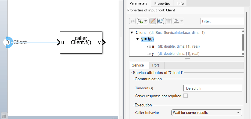
After configuring the Function Caller block, connect blocks to represent function inputs and outputs.
Add a Status Argument to Client Function Elements
To model and handle communication errors for client-server calls, add a status argument to the function prototype.
To add a status argument:
In the Property Inspector, on the Service tab, click the Add Argument dropdown and select Add Status Argument.
Edit the function prototype string directly to include a status output as the last argument. For example, change
y = f(u)to[y, status] = f(u).
The status argument has these constraints:
Each function element can have only one status argument.
The status argument appears last in the function prototype.
The data type is
SlSignalStatusand read-only.Most attribute fields (data type, dimensions, data mode, complexity) are read-only. Only the description is editable.
After adding a status argument, the Function Caller block prototype must
include the status output. For example, if the client port is named
Client, the Function Caller block prototype is
[y, status] = Client.f(u).
For more information about SlSignalStatus values and how to implement
error-handling logic, see Handle Communication Errors with Status Elements.
Note
Status arguments apply to client ports only. Server ports do not support status arguments.
Default Function Argument Attributes
When you create a new function element or add a function argument to a function element, the software creates the argument with these default attribute values:
Data type —
doubleDimensions —
1(scalar)Complexity —
real
To modify the data type, dimensions, and complexity of a function argument, select the function argument in the Property Inspector, and edit the values in the Attributes panel.
Configure Components for Data-Triggered Execution
In addition to periodic execution based on sample time, component functions can execute when new data arrives on an associated input port. Use data-triggered execution when a component must respond to incoming data rather than run on a fixed schedule—for example, processing sensor readings that arrive at irregular intervals.
To configure data-triggered execution, the software component model must be an export-function model. For more information, see Create Export-Function Model.
Note
Configure the Inport block to produce a function-call event. Set the
Output function call parameter to
'on'.
You configure data‑triggered execution semantics by setting execution properties on the associated data element.
To associate data arrival with function execution, on the Service tab, in the Execution section, set On data arrival, execute to the name of an Inport block with function-call output.
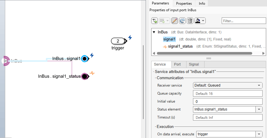
On the canvas, a trigger icon
 appears on the Inport block and its associated data element.
Data‑triggered execution affects when a function executes at run time, but does not change the functional behavior implemented inside the function.
See Also
Topics
- Simulate Software Architectures to Validate Run-time Behavior (System Composer)
- Integrate Software Components into Compositions Using Software Component Designer (System Composer)

