Simulation 3D Three-Wheeled Vehicle

Libraries:
Vehicle Dynamics Blockset /
Vehicle Scenarios /
Sim3D /
Sim3D Vehicle /
Components
Description
Note
Simulating models with the Simulation 3D Three-Wheeled Vehicle block requires Simulink® 3D Animation™.
The Simulation 3D Three-Wheeled Vehicle block implements a vehicle with three wheels in the 3D simulation environment.
To use this block, ensure that the Simulation 3D Scene Configuration
block is in your model. If you set the Sample time parameter of
this block to -1, the block uses the sample time specified in the
Simulation 3D Scene Configuration block.
The block input uses the vehicle Z-down right-handed (RH) Cartesian coordinate system defined in SAE J6701. The coordinate system is inertial and initially aligned with the vehicle geometric center:
X-axis — Along vehicle longitudinal axis, points forward
Y-axis — Along vehicle lateral axis, points to the right
Z-axis — Points downward
Tip
Verify that the Simulation 3D Three-Wheeled
Vehicle block executes before the Simulation 3D Scene
Configuration block. That way, Simulation 3D Three-Wheeled
Vehicle prepares the signal data before the Unreal Engine® 3D visualization environment receives it. To check the block execution
order, right-click the blocks and then click the Properties button
![]() . On the General tab, confirm
these Priority settings:
. On the General tab, confirm
these Priority settings:
Simulation 3D Scene Configuration —
0Simulation 3D Three-Wheeled Vehicle —
-1
For more information about execution order, see Control and Display Execution Order.
Examples
This example shows how to create a 3D environment with a three-wheeled vehicle model, similar to a tuk tuk, and view the model animation in the Simulation 3D Viewer window using Simulink®. You can use the Simulation 3D Scene Configuration (Simulink 3D Animation) block to create a 3D environment and the Simulation 3D Three-Wheeled Vehicle block to implement a three-wheeled vehicle in a 3D environment. You can then view the 3D environment in the Simulation 3D Viewer window.
Open Model
Open the Simulink model.
open_system("Sim3dTukTukExample");Explore Model
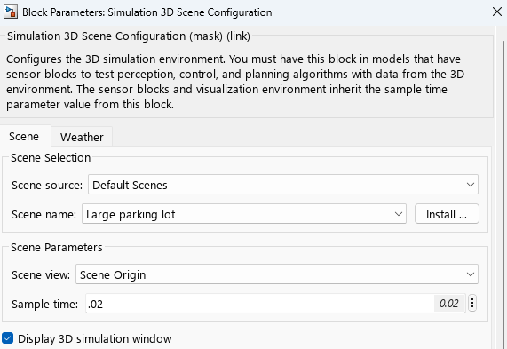
The model includes a Simulation 3D Scene Configuration block and a Simulation 3D Three-Wheeled Vehicle block. The Simulation 3D Scene Configuration (Simulink 3D Animation) block implements a 3D simulation environment. Double-click the Simulation 3D Scene Configuration block to open the Block Parameters dialog box. Set a view in the scene with the Scene view parameter. You must include the configuration block when building Simulink models with 3D blocks.
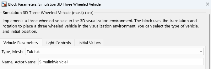
The Simulation 3D Three-Wheeled Vehicle block adds a three-wheeled vehicle to the 3D environment. Double-click the Simulation 3D Three-Wheeled Vehicle block to open the Block Parameters dialog box.
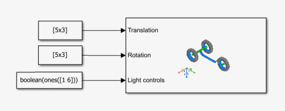
In this example, Constant blocks reposition and reorient the three-wheeled vehicle and turn specific vehicle lights on or off.
Simulate Model
Simulate the model to view the tuk tuk animation in the Simulation 3D Viewer window.
sim("Sim3dTukTukExample");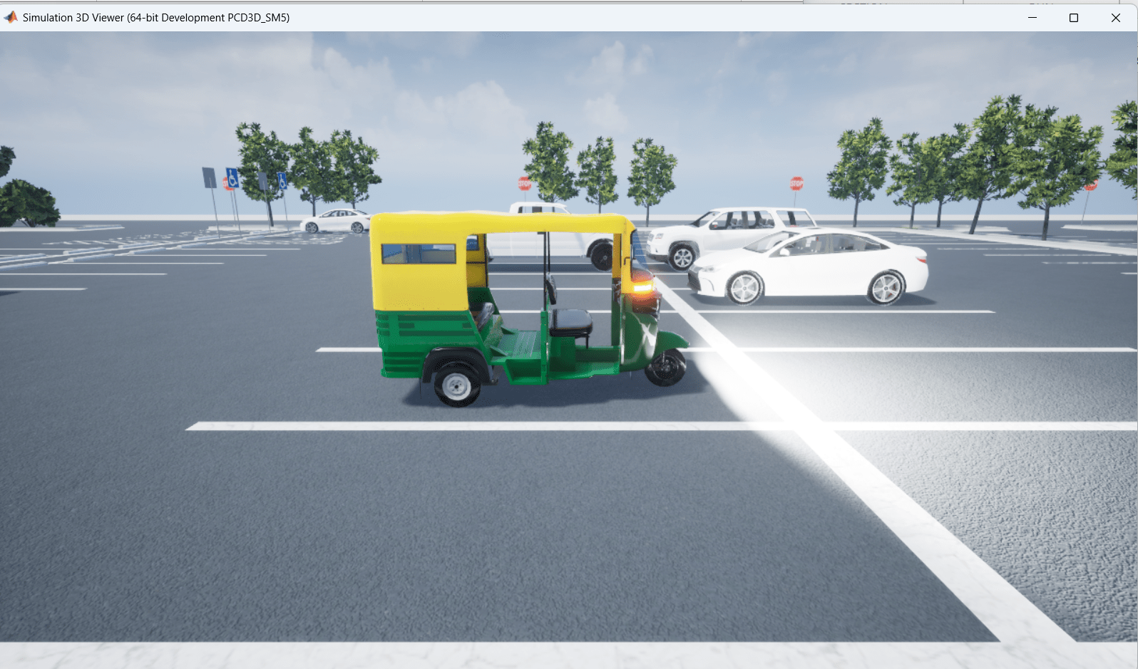
Ports
Input
Vehicle and wheel translation, in m. Array dimensions are 5-by-3.
Translation(1,1),Translation(1,2), andTranslation(1,3)— Vehicle translation along the inertial vehicle Z-down X-, Y-, and Z- axes, respectively.Translation(...,1),Translation(...,2), andTranslation(...,3)— Wheel translation relative to vehicle, along the vehicle Z-down X-, Y-, and Z- axes, respectively.
The signal contains translation information according to the axle and wheel locations.
| Translation | Array Element | Translation Axis |
|---|---|---|
Vehicle, Xv | Translation(1,1) | Inertial vehicle Z-down X-axis |
Vehicle, Yv | Translation(1,2) | Inertial vehicle Z-down Y-axis |
Vehicle, Zv | Translation(1,3) | Inertial vehicle Z-down Z-axis |
Handlebars, XH | Translation(2,1) | Inertial vehicle Z-down X-axis |
Handlebars, YH | Translation(2,2) | Inertial vehicle Z-down Y-axis |
Handlebars, ZH | Translation(2,3) | Inertial vehicle Z-down Z-axis |
Front wheel, XF | Translation(3,1) | Vehicle Z-down X-axis |
Front wheel, YF | Translation(3,2) | Vehicle Z-down Y-axis |
Front wheel, ZF | Translation(3,3) | Vehicle Z-down Z-axis |
Rear left wheel, XRL | Translation(4,1) | Vehicle Z-down X-axis |
Rear left wheel, YRL | Translation(4,2) | Vehicle Z-down Y-axis |
Rear left wheel, ZRL | Translation(4,3) | Vehicle Z-down Z-axis |
Rear right wheel, XRR | Translation(5,1) | Vehicle Z-down X-axis |
Rear right wheel, YRR | Translation(5,2) | Vehicle Z-down Y-axis |
Rear right wheel, ZRR | Translation(5,3) | Vehicle Z-down Z-axis |
Vehicle and wheel rotation, in rad. Array dimensions are 5-by-3.
Rotation(1,1),Rotation(1,2), andRotation(1,3)— Vehicle rotation about the inertial vehicle Z-down X-, Y-, and Z- axes, respectively.Rotation(...,1),Rotation(...,2), andRotation(...,3)— Wheel rotation relative to vehicle, about the vehicle Z-down X-, Y-, and Z- axes, respectively.
Note
If the yaw value provided for the front wheel differs from the yaw value provided for the handlebars, the yaw value of the handlebars is used for the front wheel. The yaw value of the handlebars and the front wheel is limited to the range of [-30, 30] degrees.
The signal contains rotation information according to the axle and wheel locations.
| Rotation | Array Element | Rotation Axis |
|---|---|---|
Vehicle, Rollv | Rotation(1,1) | Inertial vehicle Z-down X-axis |
Vehicle, Pitchv | Rotation(1,2) | Inertial vehicle Z-down Y-axis |
Vehicle, Yawv | Rotation(1,3) | Inertial vehicle Z-down Z-axis |
Handlebars, RollH | Rotation(2,1) | Inertial vehicle Z-down X-axis |
Handlebars, PitchH | Rotation(2,2) | Inertial vehicle Z-down Y-axis |
Handlebars, YawH | Rotation(2,3) | Inertial vehicle Z-down Z-axis |
Front wheel, RollF | Rotation(3,1) | Vehicle Z-down X-axis |
Front wheel, PitchF | Rotation(3,2) | Vehicle Z-down Y-axis |
Front wheel, YawF | Rotation(3,3) | Vehicle Z-down Z-axis |
Rear left wheel, RollRL | Rotation(4,1) | Vehicle Z-down X-axis |
Rear left wheel, PitchRL | Rotation(4,2) | Vehicle Z-down Y-axis |
Rear left wheel, YawRL | Rotation(4,3) | Vehicle Z-down Z-axis |
Rear right wheel, RollRR | Rotation(5,1) | Vehicle Z-down X-axis |
Rear right wheel, PitchRR | Rotation(5,2) | Vehicle Z-down Y-axis |
Rear right wheel, YawRR | Rotation(5,3) | Vehicle Z-down Z-axis |
Light controls input signal, specified as a 1-by-6 Boolean vector. Each element of the vector turns a specific vehicle light on or off, as indicated in this table. A value of 1 turns the light on; a value of 0 turns the light off.
| Vector Element | Vehicle Light |
|---|---|
(1,1) | Headlight high beam |
(1,2) | Headlight low beam |
(1,3) | Brake |
(1,4) | Reverse |
(1,5) | Left signal |
(1,6) | Right signal |
Dependencies
To create this port, on the Light Controls tab, select Enable light controls.
Data Types: Boolean
Parameters
Vehicle Parameters
Type of vehicle. By default, Type is set to
Tuk tuk. For vehicle dimensions, see Tuk tuk.
Programmatic Use
To set the block
parameter value programmatically, use the set_param
function.
To get the block
parameter value programmatically, use the get_param
function.
| Parameter: | Mesh |
| Values: | Tuk tuk (default) |
| Data Types: | character vector |
Name of vehicle. By default, when you use the block in your model, the
block sets the Name parameter to
SimulinkVehicle.
The value of XX
Programmatic Use
To set the block
parameter value programmatically, use the set_param
function.
To get the block
parameter value programmatically, use the get_param
function.
| Parameter: | ActorName |
| Values: | SimulinkVehicle1 (default) | character vector |
| Data Types: | character vector |
Sample time, Ts. The graphics frame rate is the inverse of the sample time.
Programmatic Use
To set the block
parameter value programmatically, use the set_param
function.
To get the block
parameter value programmatically, use the get_param
function.
| Parameter: | SampleTime |
| Values: | -1 (default) | scalar |
| Data Types: | double |
Initial Values
Initial vehicle and wheel translation, in m. Array dimensions are 5-by-3.
Translation(1,1),Translation(1,2), andTranslation(1,3)— Initial vehicle translation along the inertial vehicle Z-down coordinate system X-, Y-, and Z- axes, respectively.Translation(...,1),Translation(...,2), andTranslation(...,3)— Initial wheel translation relative to vehicle, along the vehicle Z-down X-, Y-, and Z- axes, respectively.
The parameter contains translation information according to the axle and wheel locations.
| Translation | Array Element | Translation Axis |
|---|---|---|
Vehicle, Xv | Translation(1,1) | Inertial vehicle Z-down X-axis |
Vehicle, Yv | Translation(1,2) | Inertial vehicle Z-down Y-axis |
Vehicle, Zv | Translation(1,3) | Inertial vehicle Z-down Z-axis |
Handlebars, XH | Translation(2,1) | Vehicle Z-down X-axis |
Handlebars, YH | Translation(2,2) | Vehicle Z-down Y-axis |
Handlebars, ZH | Translation(2,3) | Vehicle Z-down Z-axis |
Front wheel, XF | Translation(3,1) | Vehicle Z-down X-axis |
Front wheel, YF | Translation(3,2) | Vehicle Z-down Y-axis |
Front wheel, ZF | Translation(3,3) | Vehicle Z-down Z-axis |
Rear left wheel, XRL | Translation(4,1) | Vehicle Z-down X-axis |
Rear left wheel, YRL | Translation(4,2) | Vehicle Z-down Y-axis |
Rear left wheel, ZRL | Translation(4,3) | Vehicle Z-down Z-axis |
Rear right wheel, XRR | Translation(5,1) | Vehicle Z-down X-axis |
Rear right wheel, YRR | Translation(5,2) | Vehicle Z-down Y-axis |
Rear right wheel, ZRR | Translation(5,3) | Vehicle Z-down Z-axis |
Programmatic Use
To set the block
parameter value programmatically, use the set_param
function.
To get the block
parameter value programmatically, use the get_param
function.
| Parameter: | Translation |
| Values: | zeros(5,3) (default) | 5-by-3 array |
| Data Types: | double |
Initial vehicle and wheel rotation, about the vehicle Z-down X-, Y-, and Z- axes.
Array dimensions are 5-by-3.
Rotation(1,1),Rotation(1,2), andRotation(1,3)— Initial vehicle rotation about the inertial vehicle Z-down coordinate system X-, Y-, and Z- axes, respectively.Rotation(...,1),Rotation(...,2), andRotation(...,3)— Initial wheel rotation relative to vehicle, about the vehicle Z-down X-, Y-, and Z- axes, respectively.
The parameter contains rotation information according to the axle and wheel locations.
| Rotation | Array Element | Rotation Axis |
|---|---|---|
Vehicle, Rollv | Rotation(1,1) | Inertial vehicle Z-down X-axis |
Vehicle, Pitchv | Rotation(1,2) | Inertial vehicle Z-down Y-axis |
Vehicle, Yawv | Rotation(1,3) | Inertial vehicle Z-down Z-axis |
Handlebars, RollH | Rotation(2,1) | Vehicle Z-down X-axis |
Handlebars, PitchH | Rotation(2,2) | Vehicle Z-down Y-axis |
Handlebars, YawH | Rotation(2,3) | Vehicle Z-down Z-axis |
Front wheel, RollF | Rotation(3,1) | Vehicle Z-down X-axis |
Front wheel, PitchF | Rotation(3,2) | Vehicle Z-down Y-axis |
Front wheel, YawF | Rotation(3,3) | Vehicle Z-down Z-axis |
Rear left wheel, RollRL | Rotation(4,1) | Vehicle Z-down X-axis |
Rear left wheel, PitchRL | Rotation(4,2) | Vehicle Z-down Y-axis |
Rear left wheel, YawRL | Rotation(4,3) | Vehicle Z-down Z-axis |
Rear right wheel, RollRR | Rotation(5,1) | Vehicle Z-down X-axis |
Rear right wheel, PitchRR | Rotation(5,2) | Vehicle Z-down Y-axis |
Rear right wheel, YawRR | Rotation(5,3) | Vehicle Z-down Z-axis |
Programmatic Use
To set the block
parameter value programmatically, use the set_param
function.
To get the block
parameter value programmatically, use the get_param
function.
| Parameter: | Rotation |
| Values: | zeros(5,3) (default) | 5-by-3 array |
| Data Types: | double |
Light Controls
Select whether to control the vehicle headlights. Use the enabled parameters to set the light parameters, including headlight intensity.
Dependencies
Selecting this parameter:
Creates the input port
Light controls.Enables these light parameters.
Lights Light Parameters Headlights Headlight color
High beam intensity
Low beam intensity
High beam cone half angle
Low beam cone half angle
Left headlight beam orientation
Right headlight beam orientation
Brake lights Brake light intensity
Reverse lights Reverse light intensity
Turn signal lights Turn signal light intensity
Period
Pulse width
Programmatic Use
To set the block parameter
value programmatically, use the set_param
function.
To get the block parameter
value programmatically, use the get_param function.
| Parameter: | VehLightsControl |
| Values: | Off (default) | On |
| Data Types: | character vector |
Headlights
Headlight color, specified as a normalized 1-by-3 vector of RGB triplet values.
Dependencies
To enable this parameter, select Enable light controls.
Programmatic Use
To set the block parameter
value programmatically, use the set_param
function.
To get the block parameter
value programmatically, use the get_param function.
| Parameter: | HeadlightColor |
| Values: | [1,1,1] (default) | vector |
| Data Types: | double |
High beam intensity, in cd.
Dependencies
To enable this parameter, select Enable light controls.
Programmatic Use
To set the block parameter
value programmatically, use the set_param
function.
To get the block parameter
value programmatically, use the get_param function.
| Parameter: | HighBeamIntensity |
| Values: | 100000 (default) | scalar |
| Data Types: | double |
Low beam intensity, in cd.
Dependencies
To enable this parameter, select Enable light controls.
Programmatic Use
To set the block parameter
value programmatically, use the set_param
function.
To get the block parameter
value programmatically, use the get_param function.
| Parameter: | LowBeamIntensity |
| Values: | 60000 (default) | scalar |
| Data Types: | double |
High beam cone half angle, in rad.
Dependencies
To enable this parameter, select Enable light controls.
Programmatic Use
To set the block parameter
value programmatically, use the set_param
function.
To get the block parameter
value programmatically, use the get_param function.
| Parameter: | HighBeamConeAngle |
| Values: | 1.22 (default) | scalar |
| Data Types: | double |
Low beam cone half angle, in rad.
Dependencies
To enable this parameter, select Enable light controls.
Programmatic Use
To set the block parameter
value programmatically, use the set_param
function.
To get the block parameter
value programmatically, use the get_param function.
| Parameter: | LowBeamConeAngle |
| Values: | 1.22 (default) | scalar |
| Data Types: | double |
Pitch and yaw orientation of the left headlight beam orientation in the
Z-down coordinate system, specified as a 1-by-2 vector,
in rad. The first element of the vector, [1,1], is the pitch
angle. The second element of the vector, [1,2], is the yaw
angle.
Dependencies
To enable this parameter, select Enable light controls.
Programmatic Use
To set the block parameter
value programmatically, use the set_param
function.
To get the block parameter
value programmatically, use the get_param function.
| Parameter: | LeftHeadlightOrientation |
| Values: | [0,0] (default) | vector |
| Data Types: | double |
Pitch and yaw orientation of the right headlight beam orientation in the
Z-down coordinate system, specified as a 1-by-2 vector,
in rad. The first element of the vector, [1,1], is the pitch
angle. The second element of the vector, [1,2], is the yaw
angle.
Dependencies
To enable this parameter, select Enable light controls.
Programmatic Use
To set the block parameter
value programmatically, use the set_param
function.
To get the block parameter
value programmatically, use the get_param function.
| Parameter: | RightHeadlightOrientation |
| Values: | [0,0] (default) | vector |
| Data Types: | double |
Brake Lights
Brake light intensity, in cd/m^2.
Dependencies
To enable this parameter, select Enable light controls.
Programmatic Use
To set the block parameter
value programmatically, use the set_param
function.
To get the block parameter
value programmatically, use the get_param function.
| Parameter: | BrakelightIntensity |
| Values: | 500 (default) | scalar |
| Data Types: | double |
Reverse Lights
Reverse light intensity, in cd/m^2.
Dependencies
To enable this parameter, select Enable light controls.
Programmatic Use
To set the block parameter
value programmatically, use the set_param
function.
To get the block parameter
value programmatically, use the get_param function.
| Parameter: | ReverselightIntensity |
| Values: | 500 (default) | scalar |
| Data Types: | double |
Turn Signal Lights
Turn signal light intensity, in cd/m^2.
Dependencies
To enable this parameter, select Enable light controls.
Programmatic Use
To set the block parameter
value programmatically, use the set_param
function.
To get the block parameter
value programmatically, use the get_param function.
| Parameter: | SignallightIntensity |
| Values: | 500 (default) | scalar |
| Data Types: | double |
Turn signal light period, in s.
Dependencies
To enable this parameter, select Enable light controls.
Programmatic Use
To set the block parameter
value programmatically, use the set_param
function.
To get the block parameter
value programmatically, use the get_param function.
| Parameter: | SignallightPeriod |
| Values: | 1 (default) | scalar |
| Data Types: | double |
Turn signal light pulse width, specified as a percent of the period.
Dependencies
To enable this parameter, select Enable light controls.
Programmatic Use
To set the block parameter
value programmatically, use the set_param
function.
To get the block parameter
value programmatically, use the get_param function.
| Parameter: | SignalPulseWidth |
| Values: | 50 (default) | scalar |
| Data Types: | double |
More About
To control the lights of vehicles in a scene:
Install the Vehicle Dynamics Blockset™ Interface for Unreal Engine Projects support package. See Customize 3D Scenes for Vehicle Dynamics Simulations.
On the block Light Controls tab, select Enable light controls.
Use the enabled parameters to specify the vehicle lights for:
Headlights
Brake lights
Reverse lights
Turn signal lights
Connect Boolean light control signals to the Signal lights input port.
Version History
Introduced in R2023bSimulating models with the Simulation 3D Three-Wheeled Vehicle block requires Simulink 3D Animation.
See Also
MATLAB Command
You clicked a link that corresponds to this MATLAB command:
Run the command by entering it in the MATLAB Command Window. Web browsers do not support MATLAB commands.
Seleccione un país/idioma
Seleccione un país/idioma para obtener contenido traducido, si está disponible, y ver eventos y ofertas de productos y servicios locales. Según su ubicación geográfica, recomendamos que seleccione: .
También puede seleccionar uno de estos países/idiomas:
Cómo obtener el mejor rendimiento
Seleccione China (en idioma chino o inglés) para obtener el mejor rendimiento. Los sitios web de otros países no están optimizados para ser accedidos desde su ubicación geográfica.
América
- América Latina (Español)
- Canada (English)
- United States (English)
Europa
- Belgium (English)
- Denmark (English)
- Deutschland (Deutsch)
- España (Español)
- Finland (English)
- France (Français)
- Ireland (English)
- Italia (Italiano)
- Luxembourg (English)
- Netherlands (English)
- Norway (English)
- Österreich (Deutsch)
- Portugal (English)
- Sweden (English)
- Switzerland
- United Kingdom (English)