Periodic CAN Message Transmission Behavior in Simulink
This example shows how to set up periodic transmission and reception of CAN messages in Simulink® using MathWorks® virtual CAN channels. The virtual channels are connected in a loopback configuration.
Vehicle Network Toolbox™ provides Simulink blocks for transmitting and receiving live messages via Simulink models over Controller Area Networks (CAN). This example uses the CAN Configuration, CAN Pack, CAN Transmit, CAN Receive and CAN Unpack blocks to perform data transfer over a CAN bus.
Transmit and Receive CAN Messages
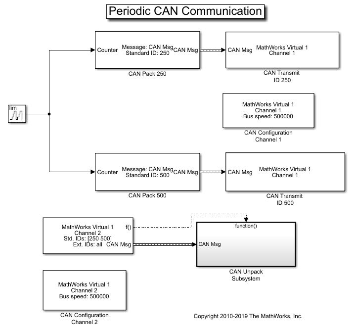
Create a model to transmit two messages at different periods, receive only specified messages and unpack the message with a specified ID.
Use a CAN Transmit block to transmit the CAN message with ID 250 to transmit messages every 1 second.
Use another CAN Transmit block to transmit the CAN message with ID 500 to transmit messages every 0.5 seconds.
Input a signal to both CAN Pack blocks to an auto-incrementing counter with a limit of 50.
Both CAN Transmit blocks are connected to MathWorks virtual channel 1.
Use a CAN Receive block to receive CAN messages from MathWorks virtual channel 2. Set the block to:
Receive messages with ID 250 and 500 only.
The Receive block generates a function call trigger if it receives a new message at any particular timestep.
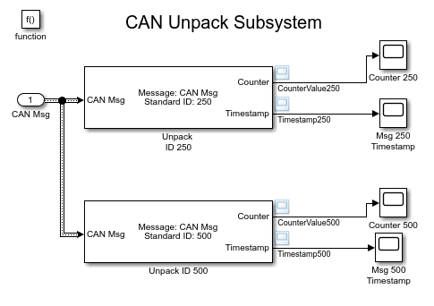
The CAN Unpack blocks are in a Function-Call Subsystem (Simulink). The subsystem is executed only when a new message is received by the CAN Receive block at a particular timestep.
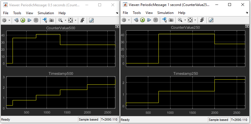
Visualize Messages at Different Timestamps
Plot the results to see the counter value and timestamp for each unpacked message. The X-axis on the plot corresponds to the simulation timestep. The timestamp plots show that the messages are sent at the specified times. It can also be seen that the number of messages transmitted for ID 250 is half as much transmitted for ID 500 due to the different periodic rates specified for them.
Extend the Example
MathWorks virtual CAN channels were used for this example. You can however connect your models to other supported hardware. You can also modify the model to transmit at different rates or transmit a combination of periodic and non-periodic messages.
This example uses the CAN blocks, but the concept demonstrated also applies to the CAN FD blocks in Simulink.