DVB-S2X BCH Decoder
R2026bDecode and recover message from BCH codeword according to DVB-S2X standard
Since R2026b
DVB-S2X BCH Decoder block
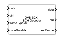
To add a block to a model, double-click the canvas and start typing the block name. Then, select the block from the list.
Libraries:
Wireless HDL Toolbox /
Error Detection and Correction
Description
The DVB-S2X BCH Decoder block decodes and recovers messages from a Bose-Chaudhuri-Hocquenghem (BCH) codeword according to the Digital Video Broadcasting Satellite Second Generation (DVB-S2X) standard [1]. The block accepts low-density parity-check (LDPC) decoded codeword data bits and a stream of control signals. It outputs decoded message data bits, a stream of control signals, a signal that indicates when the block is ready to accept new input, and an optional signal that provided the number of corrected errors in the output. The block supports either a scalar or an 8-element column vector as input.
The block supports three forward error correction (FEC) frame types, normal, short, and medium. The block provides an architecture suitable for HDL code generation and hardware deployment. You can use this block in a DVB-S2X receiver for satellite communication.
Examples
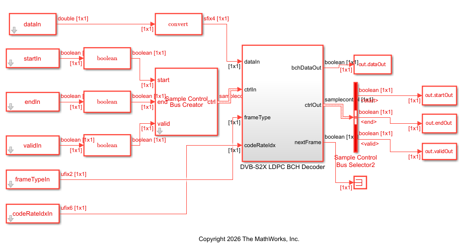
Decode and Recover Message Using DVB-S2X Standard FEC Decoder
Decode and recover message from codeword using FEC decoder according to DVB-S2X standard.
Ports
Input
Output
Parameters
More About
Algorithms
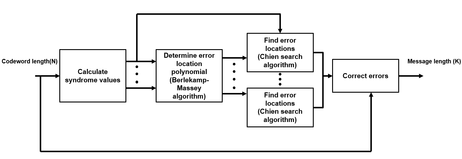
The DVB-S2X BCH Decoder block decodes BCH-encoded codewords by detecting and correcting errors in the received data. For each input frame, the block performs these operations:
Calculate syndrome values — The block computes syndromes from the received codeword. The syndromes indicate whether errors are present in the input data. This operation occurs during the input phase and does not add additional latency.
Determine error locator polynomial — The block determines the error location polynomial using the Berlekamp-Massey algorithm. This polynomial identifies the locations of errors in the codeword. For more information about the Berlekamp-Massey algorithm, see Algorithms for BCH and RS Errors-only Decoding.
Find error locations and error correction — The block evaluates the error locator polynomial using Chien search [2] algorithm to determine the error locations, and correct errors. To improve throughput for DVB-S2X applications, the block evaluates multiple candidates of the error locator polynomial in parallel. When the input data is specified as a vector, the block processes multiple symbols per clock cycle and performs error location detection concurrently across these symbols. This parallel evaluation reduces the number of clock cycles required for error detection compared to scalar processing.
The latency between valid input data and the corresponding valid output data depends on
the input dimension, frame type, code rate, and the number of errors the block can correct.
The block determines the latency primarily from the Chien search stage, which evaluates
error locations across the BCH codeword. This stage dominates the decoding time because it
processes the entire codeword of length
NBCH.
For scalar processing, the block performs one operation per cycle and requires
approximately NBCH clock cycles.
For vector processing, the block processes multiple samples in parallel and reduces the
latency proportionally. For example, when the input vector size is 8, the latency reduces to
approximately NBCH/8.
The block can generate output samples while the Chien search is still in progress, which reduces the effective latency compared to designs that wait until the entire decoding operation completes. The latency depends on the selected FEC frame type because the codeword length varies across frame types. Normal frames have the highest latency, followed by medium frames and short frames. The output end signal aligns with the completion of decoding for each input codeword.
This figure shows a Logic Analyzer waveform of the sample output and latency of the
DVB-S2X BCH Decoder block for a scalar input when you set the FEC
frame type and Code rate values to
Normal and 90/180, respectively. The
latency of the block is 35,302 cycles.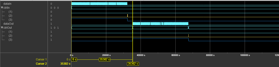
This figure shows a Logic Analyzer waveform of the sample output and latency of the
DVB-S2X BCH Decoder block for a vector input when you set the FEC
frame type and Code rate values to
Normal and 90/180, respectively. The
latency of the block is 6791 cycles.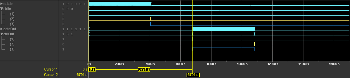
References
[1] ETSI Standard EN 302 307-2 V1.1.1: Digital Video Broadcasting (DVB); Second generation framing structure, channel coding and modulation systems for Broadcasting, Interactive Services, News Gathering and other broadband satellite applications, DVB-S2 Extensions (DVB-S2X),European Telecommunications Standards Institute, Valbonne, France, 2005-03.
[2] Chien, R. “Cyclic Decoding Procedures for Bose- Chaudhuri-Hocquenghem Codes.” IEEE Transactions on Information Theory 10, no. 4 (October 1964): 357–63. https://doi.org/10.1109/TIT.1964.1053699.
Extended Capabilities
Version History
Introduced in R2026b

