Hybrid MoM-PO Method for Metal Antennas with Large Scatterers
Hybrid method of moments (MoM) and physical optics (PO) computational technique in Antenna Toolbox™ allows you to model antennas near large scatterers such as parabolic reflectors. The antenna element is modeled using MoM while the effect of electrically large structures is considered using PO.
Subdomain RWG Basis Functions and Extra Dimensions
The familiar Rao-Wilton-Glisson (RWG) basis functions on triangles are based on [2].
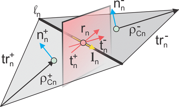
In the image, for two arbitrary triangular patches trn+ and trn- having areas An+ and An- and sharing a common edge ln the basis functions has the form
where is the vector drawn from the free vertex of the triangle trn+ to the observation point ; is the vector drawn from the observation point to the free vertex of the triangle trn-. The basis function is zero outside the two adjacent triangles. The RWG vector basis function is linear and has no flux (that is, has no normal component) through its boundary.
From [1], along with the standard definition, this method requires two unit normal vectors and two-unit vectors also shown in the figure. Vector is the plane of triangle trn+; both vectors are perpendicular to the edge ln. They are defined at the center of edge, which isln denoted by . Directions of
are also shown in the figure. This technique assumes that the normal vectors are properly (angle between adjacent must be less than 180 degrees) and uniquely defined. Specific vector orientation (e.g. outer or inner normal vectors) does not matter. We then form two cross product vectors ,
and establish that both such unit vectors directed along the edge are identical,
Only vector is eventually needed.
MoM Region and PO Region
The surface current density, , on the entire metal surface is expanded into N RWG basis functions. However, a part of such basis functions belongs to the MoM region (or "exact region") while another part will belong to the PO region (or "approximate region"). These basis functions (or regions) can overlap and be arbitrarily distributed in space (not necessarily be contiguous). The method assumes that NMoM basis functions from the MoM region up front in the list and NPO basis functions for the PO region afterward. Therefore, you have
MoM Solution and PO Solution
If there is no PO region, you can solve the entire problem using the MoM with single square MoM system matrix , which may be subdivided into 4 matrices as shown.
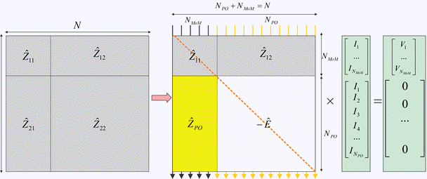
The figure shows the matrix interpretation of the hybrid MoM-PO solution and its comparison with plain MoM solution. The method assumes the antenna feeds gives the vector, that describes the excitation, which belongs to the MoM region only.
The hybrid solution keeps submatrices and . In other words, the method solves the standard system of the linear equations for the MoM region where radiation from the PO region via is considered.
The hybrid solution ignores the submatrices, entirely. Here, the currents in the PO region do not interact with each other. They are found via the radiated magnetic field, , from the MoM region, using PO approximation [1]. A new matrix describes this operation, , and negative identity matrix, E, which replaces .
Finding ZPO
The suitable PO approximation has the form [1]
where δ accounts for the shadowing effects. If the observation point lies in the shadow region, δ must be zero. Otherwise it equals ±1 depending on the direction of incidence with respect to the orientation normal vector . Using second Eq.(4) yields:
Reference [1] outlines an elegant way to express unknowns InPO explicitly, using an interesting variation of the collocation method. First, we consider a collocation point that tends to the edge center of a certain basis function and is in its plus triangle. We then multiply Eq. (7) by vector . Since the normal component of the basis function under interest at the edge is one and all other basis functions sharing the same triangle have no normal component at this edge, the result becomes
Repeat the same operation with the minus triangle and obtain
Add both Eqs. (8a) and (8b) together, divide the result by two, and transform the triple vector product to obtain
Therefore, according to Eqs. (2) and (3),
To complete the derivation, the H-field radiated by the MoM region is always written in the form
where are given by individual basis function contributions. In the simplest case, every such contribution is the dipole radiation [3]. Substitution of Eq. (11) into Eq. (10) yields
Direct Solution Method
According to the second figure, the coupled system of equations has the form
The direct solution method results in the substitution of the expression for the PO current into the first equation,
Note
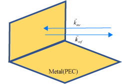
The classic physical optics (PO) formulation does not support multiple reflections from a physical structure illuminated by a plane wave. The PO current density is valid only in the illuminated region of the structure. This formulation does not handle any reflections from the illuminated region that result in secondary illumination of a different region of the structure.
Case 1: When the direction of the incident plane wave results in a reflection back in the direction of the incoming source.
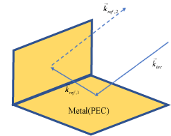
Case 2: When the angle of the incident plane wave causes a second reflection from a different part of the structure, this reflection contributes significantly to the scattered field and is not considered by the PO solver.
.
References
[1] U. Jakobus and F. M. Landstorfer, “Improved PO-MM Formulation for Scattering from Three-Dimensional Perfectly Conducting Bodies of Arbitrary Shape,” IEEE Trans. Antennas and Propagation, vol. AP-43, no. 2, pp. 162-169, Feb. 1995.
[2] S. M. Rao, D. R. Wilton, and A. W. Glisson, “Electromagnetic scattering by surfaces of arbitrary shape,” IEEE Trans. Antennas and Propagation, vol. AP-30, no. 3, pp. 409-418, May 1982.
[3] S. Makarov, Antenna and EM Modeling in MATLAB, Wiley, New York, 2002.