Model AUTOSAR Adaptive Service Communication
The AUTOSAR Adaptive Platform defines service-oriented, event-based communication between adaptive software components. Each adaptive software component provides and consumes services, and interconnected components send and receive service events. A component contains:
An algorithm that performs tasks in response to received events.
Required and provided ports, through which events are received and sent.
Service interfaces, which provide the framework for event-based communication.
To model adaptive service communication in Simulink®, you can:
Create AUTOSAR required and provided ports, service interfaces, service interface events, and C++ namespaces.
Create root-level inports and outports and map them to AUTOSAR required and provided ports and service interface events.
If you have Simulink Coder™ and Embedded Coder® software, you can generate C++ code and ARXML descriptions for AUTOSAR service communication.
To implement adaptive service communication in Simulink:
Open a model configured for the AUTOSAR Adaptive Platform. Displays in this example use model
autosar_LaneGuidance.Open the AUTOSAR Dictionary and select Service Interfaces. To create an AUTOSAR service interface, click the Add button
 . In the Add Interfaces dialog box, specify
the interface name and the number of associated events.
. In the Add Interfaces dialog box, specify
the interface name and the number of associated events.
Expand the Service Interfaces node. Expand the new service interface and select Events. In the events view, select each service event and configure its attributes.

Select Namespaces. The namespaces view allows you to define a unique namespace for each service interface. The code generator uses the defined namespace when producing C++ code for the interface. To modify or construct a namespace specification, select a namespace element and edit the name value. For example, this namespaces view defines namespace
company::chassis::providedfor service interfaceProvidedInterface.
At the top level of the AUTOSAR Dictionary, expand AdaptiveApplications and expand the adaptive software component. Use the RequiredPorts and ProvidedPorts views to add AUTOSAR required and provided ports that you want to associate with the new service interface. For each new service port, select the service interface you created.

Optionally, you can configure adaptive service instance identifier for AUTOSAR ports. In the RequiredPorts or ProvidedPorts view, select a port and view its Manifest attributes. If Instance Identifier is selected to identify the service instance, examine the value for Instance Identifier. You can enter a value or accept an existing value. For more information, see Configure AUTOSAR Adaptive Service Instance Identifier.
Optionally, for AUTOSAR required ports, you can configure service discovery, which affects how adaptive applications find dynamic services. In the RequiredPorts view, select a port and configure its Service Discovery Mode. Select
OneTimeorDynamicDiscovery. For more information, see Configure AUTOSAR Adaptive Service Discovery Modes.In the model window, to model AUTOSAR adaptive service ports, create root-level inports and outports.
Open the Code Mappings editor. Use the Inports and Outports tabs to map Simulink inports and outports to AUTOSAR required and provided ports. For each inport or outport, select an AUTOSAR required or provided port and an AUTOSAR service interface event.

Optionally, you can configure memory allocation for service data sent from AUTOSAR provided ports. In the Outports tab, select a port and use the code attribute
AllocateMemoryto configure memory allocation. Specify whether to send event data by reference (the default) or byara::comallocated memory. To send event data byara::comallocated memory, select the valuetrue. To send event data by reference, selectfalse. For more information, see Configure Memory Allocation for AUTOSAR Adaptive Service Data.After validating the adaptive component model configuration, you can simulate or generate code for AUTOSAR service communication.
To programmatically configure AUTOSAR adaptive service communication, use the AUTOSAR property and mapping functions. For example, the following MATLAB® code adds an AUTOSAR service interface, event, and required port to an open model. It then maps a Simulink inport to the AUTOSAR required port.
hModel = 'autosar_LaneGuidance';
openExample(hModel);

% Add AUTOSAR service interface mySvcInterface with event mySvcEvent
arProps = autosar.api.getAUTOSARProperties(hModel);
addPackageableElement(arProps,'ServiceInterface',...
    '/LaneGuidance_pkg/LaneGuidance_if','mySvcInterface');
add(arProps,'mySvcInterface','Events','mySvcEvent');

% Add AUTOSAR required port myRPort, associated with mySvcInterface
add(arProps,'LaneGuidance','RequiredPorts','myRPort',...
    'Interface','mySvcInterface');

% Map Simulink inport to AUTOSAR port/event pair myRPort and mySvcEvent
slMap = autosar.api.getSimulinkMapping(hModel);
mapInport(slMap,'rightCarInBlindSpot','myRPort','mySvcEvent');
Model Client-Server Communication
Adaptive AUTOSAR supports client-server communication between application software components. Methods on an AUTOSAR service interface define the interaction between a software component modeled as a server that provides an interface implementation and a software component modeled as a client that requires an interface.
In Simulink, you can model client-server communication with synchronous or asynchronous call behaviors. Synchronous client models produce blocked client execution, where the client sends requests to the server and waits for the response. Asynchronous client models produce non-blocking execution, which consists of clients sending requests, continuing execution after the request is sent, and processing the response upon method completion.
To model AUTOSAR clients and servers in the Simulink environment for simulation and code generation:
Model AUTOSAR servers by using Simulink Function blocks at the root level of a model.
Model synchronous or asynchronous AUTOSAR clients:
Model synchronous client calls by using Function Caller blocks.
Model asynchronous client calls by using Function Caller blocks and Message Triggered Subsystem blocks.
If you import ARXML definitions of clients or servers, AUTOSAR Blockset creates and configures the components in Simulink, after which you can directly simulate the component models and export generated C++ code and ARXML. ARXML definitions of clients are imported as synchronous client calls, which you can reconfigure in Simulink to use asynchronous behavior if needed.
Configure AUTOSAR Adaptive Servers
A server provides services to clients. To model and simulate an AUTOSAR adaptive server in the Simulink environment, use a Simulink Function block and Function Element block to provide the service to clients. Optionally, you can generate C++ code and export ARXML definitions.
Create or open an export-function model configured for the AUTOSAR Adaptive Platform.
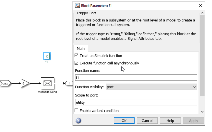
Model the AUTOSAR adaptive server. Use Simulink Function blocks and Function Element ports to model provided services to clients.

Open the Simulink Function block and double-click the Trigger Port block to open the Block Parameters. Enable Treat as Simulink function and set Function visibility to
portand Scope to port is set to the name of the exporting function port created by the root-level Function Element.If you are modeling asynchronous client-server behavior, select Execute function call asynchronously.
On the Apps tab, click AUTOSAR Component Designer.
View the AUTOSAR properties of the service interface.
Open the AUTOSAR Dictionary and view the properties derived from the component model. Optionally, you can create additional properties:
Select Service Interfaces to view or create an interface. This interface defines the properties for the modeled server component.
To create an AUTOSAR service interface, click the add button
. Under Service Interfaces, view or create the methods. The AUTOSAR adaptive standard defines request-response methods that expect a response to a method call and fire-forget methods that do not expect a return value. For the modeled server, you can create and configure the name and method type.
At the top level of the AUTOSAR Dictionary, expand AdaptiveApplications and view ProvidedPorts. The ProvidedPorts define the properties for the ports used in Simulink Function blocks to respond to clients.
For a deployed server to communicate with deployed clients, the service instance identification of the provided port of the modeled server must match the instance identification of the required port of the modeled clients. For more information, see Configure AUTOSAR Adaptive Service Instance Identifier.
View how the code properties map to the modeled server. Open the Code Mappings editor, then open the Functions tab to view server functions.
The Source column shows the modeled Function Element blocks.
The Port column shows the ProvidedPort name.
The Method column shows which method defined in the AUTOSAR Dictionary associates with each port and block.
Validate and simulate the server model.
Optionally build the component model to generate C++ code and export ARXML definitions.
Configure Synchronous AUTOSAR Adaptive Clients (Blocking)
Configure an AUTOSAR adaptive client that requires a service from a server. The client in this example models synchronous communication, resulting in blocked execution after sending the request to the server.
To model a synchronous AUTOSAR adaptive client in the Simulink environment, use a Simulink Function Caller block and configure a service interface to call the server. Optionally, you can generate C++ code and export ARXML definitions.
Create or open an export-function model configured for the AUTOSAR Adaptive Platform.
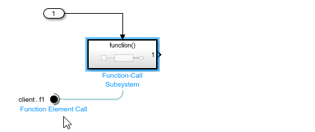
Model the synchronous AUTOSAR adaptive client. To model the client in the Simulink, use Function Caller blocks and Function Element Call blocks to call the service provided by the server.
Continue to Validate, Simulate, and Optionally Generate Code for Adaptive Clients.
Configure Asynchronous AUTOSAR Adaptive Clients (Non-blocking)
Configure an AUTOSAR adaptive client that requires a service from a server. The client in this example models asynchronous communication, resulting in non-blocking operations with continued execution after sending the request to the server.
To model an asynchronous AUTOSAR adaptive client in the Simulink environment, use a Simulink Function Caller block and a Message Triggered subsystem, and configure the service interface to call the server. Optionally, you can generate C++ code and export ARXML definitions.
To configure an asynchronous adaptive client:
Create or open an export-function model configured for the AUTOSAR Adaptive Platform.
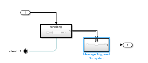
Add a Function Element Call port to model the asynchronous AUTOSAR adaptive client.
In the function-call subsystem, add a Function Caller block and open the Block Parameters. In the Block Parameters dialog box, select Execute function call asynchronously.
The asynchronous function-call block must have one output. When asynchronous behavior is selected, the Function Caller block emits a message instead of signal lines. The message signifies the asynchronous behavior of method execution.

At the root level of the model, add a Message Triggered Subsystem and connect the message signal from the Function-Call Subsystem.
When the method called from the Function Caller completes, the output message triggers the message triggered subsystem, which acts as the callback that the client application registers for an asynchronous method. The message triggered subsystem executes whenever a message is available at the control port, independent of sample time.
Open the message triggered subsystem, and open the Block Parameters for the Trigger Port block.
In the Block Parameters dialog box, verify that Trigger type is set to
message, and Schedule as aperiodic partition is not selected.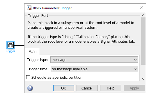
Add behavior to the message triggered subsystem.
Complete the model with any additional logic.
Continue to section Validate, Simulate, and Optionally Generate Code for Adaptive Clients.
Validate, Simulate, and Optionally Generate Code for Adaptive Clients
To validate and simulate an AUTOSAR adaptive client in the Simulink environment, review the service interface by using the AUTOSAR Dictionary and code property mappings by using the Code Mapping editor. Optionally, you can generate C++ code and export ARXML definitions.
On the Apps tab, click AUTOSAR Component Designer.
View the AUTOSAR properties of the service interface. Open the AUTOSAR Dictionary and view the properties derived from the component model. Optionally, you can create additional properties:
Select Service Interfaces to view or create an interface. This interface defines the properties for the modeled client component.
To create an AUTOSAR service interface, click the add button
. Under Service Interfaces, view or create the methods. For the modeled client, you can create and configure the name and method type.
At the top level of the AUTOSAR Dictionary, expand AdaptiveApplications, and view the RequiredPorts. RequiredPorts define the code properties for the ports used in Simulink Function Caller blocks that request services from servers.
For a deployed client to communicate with deployed servers, the service instance identifier of the required port of the modeled client must match the instance identifier of the provided port of the modeled server. For more information, see Configure AUTOSAR Adaptive Service Instance Identifier.
View how the code properties map to the modeled client. Open the Code Mappings editor, then open the Function Callers tab to view client functions.
The Source column shows the modeled Function Caller blocks.
The Port column shows the RequiredPort name.
The Method column shows which method defined in the AUTOSAR Dictionary associates with each port and block.
Validate and simulate the client model.
(Optional) Build the component model to generate C++ code and export ARXML definitions.
Tips and Limitations
Global Simulink functions are not supported for Adaptive AUTOSAR.
Private scoped Simulink functions are not mapped to methods. They can be used to model behavior internal to the adaptive application component.
Function Caller blocks configured for asynchronous behavior must have one output. Function Caller blocks with a void output or multiple outputs are not supported.
See Also
Simulink Function | Function Caller | Function-Call Subsystem | Message Triggered Subsystem | Function Element | Function Element Call