comm.CPMDemodulator
Demodulate signal using CPM method and Viterbi algorithm
Description
The comm.CPMDemodulator
System object™ demodulates an input signal that was modulated using the continuous phase
modulation (CPM) method. The input is a baseband representation of the modulated signal. For
more information about the demodulation and filtering applied, see Algorithms.
To demodulate a signal that was modulated using the CPM method:
Create the
comm.CPMDemodulatorobject and set its properties.Call the object with arguments, as if it were a function.
To learn more about how System objects work, see What Are System Objects?
Creation
Syntax
Description
cpmdemod = comm.CPMDemodulator creates a demodulator System object to demodulate input CPM signals using the Viterbi algorithm.
cpmdemod = comm.CPMDemodulator(
sets properties using one or more name-value arguments. For example,
Name=Value)comm.CPMDemodulator(SymbolMapping='Gray') configures the object with
gray-coded symbol ordering for the modulated symbols.
cpmdemod = comm.CPMDemodulator(
sets the M,Name=Value)ModulationOrder property to
M and optional name-value arguments.
Properties
Unless otherwise indicated, properties are nontunable, which means you cannot change their
values after calling the object. Objects lock when you call them, and the
release function unlocks them.
If a property is tunable, you can change its value at any time.
For more information on changing property values, see System Design in MATLAB Using System Objects.
Modulation order, specified as a power-of-two scalar. The modulation order M = 2k specifies number of points in the symbol alphabet. k is a positive integer indicating the number of bits per symbol.
Option to output data as bits, specified as 0
(false) or 1 (true).
Set this property to
falseto output data as integers.Set this property to
trueto output data as bits.
For more information, see Integer-Valued and Binary-Valued Output Signals.
Demodulation decision method, specified as 'Hard decision' or
'Approximate log-likelihood ratio'.
When you set this property to
'Hard decision', the outputYis returned as a column vector with element values of0or1. The output data type is specified byOutputDataType.When you set this property to
'Approximate log-likelihood ratio', the output data type is the same as the inputX. For the approximate log-likelihood ratio, the object generates positive values for 0s and negative values for 1s.
For more information, see Algorithms.
Dependencies
This property applies when you set BitOutput to
true.
Source of noise variance, specified as 'Property' or
'Input port'.
Dependencies
This property applies when you set BitOutput to
true and DecisionMethod to 'Approximate log-likelihood
ratio'.
Noise variance, specified as a positive scalar.
Tunable: Yes
Dependencies
This property applies when you set BitOutput to
true, VarianceSource to 'Property', and DecisionMethod to 'Approximate log-likelihood
ratio'.
Data Types: double
Symbol mapping, specified as 'Binary' or
'Gray'. This property determines how each integer maps to a group
of output bits.
Set this property to
'Binary'to map symbols using binary-coded ordering.Set this property to
'Gray'to map symbols using Gray-coded ordering.
Dependencies
To enable this property, set the BitOutput property to
true.
Modulation index {hi}, specified as a nonnegative scalar or column vector. The modulator operates in multi-h. For more information, see CPM Demodulation.
Data Types: double
Type of frequency pulse shaping used by the modulator to smooth the phase
transitions of the modulated signal, specified as 'Rectangular',
'Raised Cosine', 'Spectral Raised Cosine',
'Gaussian', or 'Tamed FM'. For more information,
see Pulse Shape Filtering.
Main lobe duration of the largest lobe in the spectral raised cosine pulse, specified as a positive integer representing the number of symbol intervals used by the demodulator to pulse-shape the modulated signal.
Dependencies
To enable this property, set the FrequencyPulse property to
'Spectral Raised Cosine'.
Data Types: double
Roll-off factor of the spectral raised cosine pulse, specified as a scalar in the range [0, 1].
Dependencies
To enable this property, set the FrequencyPulse property to
'Spectral Raised Cosine'.
Data Types: double
Product of the bandwidth and symbol time of the Gaussian pulse shape, specified as a
positive scalar. Use BandwidthTimeProduct to reduce the bandwidth,
at the expense of increased intersymbol interference.
Dependencies
To enable this property, set the FrequencyPulse property to
'Gaussian'.
Data Types: double
Length of the frequency pulse shape in symbol intervals, specified as a positive integer. For more information on the frequency pulse length, refer to LT in Pulse Shape Filtering.
Data Types: double
Symbol prehistory, specified as scalar or vector with odd integer elements. Values
must be in the range [–(M – 1), (M – 1)]. M is the modulation order specified by ModulationOrder. The SymbolPrehistory
property defines the data symbols used by the modulator before the first call of the
object, in reverse chronological order.
A scalar value expands to a vector of length
PulseLength– 1.For a vector, the length must be
PulseLength– 1.
Data Types: double
Initial phase offset in radians, specified as a scalar. This parameter value is initial phase offset of the modulated waveform.
Symbol sampling rate, specified as a positive integer. This property specifies the input symbol downsampling factor for each output sample.
Tip
To accurately model nonbinary pulse shapes, specifically pulse shapes other than rectangular, you should set the symbol sampling rate to values greater than 4.
Data Types: double
Traceback depth for the Viterbi algorithm, specified as a positive integer representing the number of trellis branches that the Viterbi algorithm uses to construct each traceback path. The value of this property is also the output delay and the number of zero symbols that precede the first meaningful demodulated symbol in the output. For more information, see Traceback Depth and Output Delays.
Data Types: double
Data type of the output, specified as 'double',
'int8', 'int16', 'int32',
'int32', 'uint8', 'uint16',
'uint32', or 'logical'.
When you set the
BitOutputproperty tofalse, you can set the output to double-precision, single-precision, or signed-integer data types.When you set the
BitOutputproperty totrue, you can set the output to double-precision, single-precision, signed-integer, unsigned-integer, or logical data types.
Dependencies
This property applies when you set BitOutput to
false or when you set BitOutput to true and DecisionMethod to 'Hard decision'.
Usage
Syntax
Input Arguments
CPM-modulated signal, specified as a column vector with a length equal to an
integer multiple of the SamplesPerSymbol.
This object accepts variable-size inputs. After the object is locked, you can change the frame size (number of rows) of the signal during simulation. For more information, see Variable-Size Signals in Code.
Data Types: double | single
Complex Number Support: Yes
Noise variance, specified as a positive scalar value.
Dependencies
This property applies when you set BitOutput to
true, VarianceSource to 'Input port', and DecisionMethod to 'Approximate log-likelihood
ratio'.
Data Types: double | single
Output Arguments
Demodulated output signal, returned as a column vector or matrix. The output
signal has a delay equal to the TracebackDepth property
value.
For more information, see Integer-Valued and Binary-Valued Output Signals and Traceback Depth and Output Delays.
Data Types: single | double | int8 | int16 | int32 | uint8 | uint16 | uint32 | logical
Object Functions
To use an object function, specify the
System object as the first input argument. For
example, to release system resources of a System object named obj, use
this syntax:
release(obj)
Examples
Create CPM modulator, and CPM demodulator System objects.
cpmmodulator = comm.CPMModulator(8, ... 'BitInput',true, ... 'SymbolMapping','Gray'); cpmdemodulator = comm.CPMDemodulator(8, ... 'BitOutput',true, ... 'SymbolMapping','Gray');
Create an error rate calculator System object™, that accounts for the delay caused by the Viterbi algorithm.
delay = log2(cpmdemodulator.ModulationOrder) ... * cpmdemodulator.TracebackDepth; errorRate = comm.ErrorRate('ReceiveDelay',delay);
Transmit 100 3-bit words and print the error rate results.
for counter = 1:100 data = randi([0 1],300,1); modSignal = cpmmodulator(data); noisySignal = awgn(modSignal,0); receivedData = cpmdemodulator(noisySignal); errorStats = errorRate(data,receivedData); end fprintf('Error rate = %f\nNumber of errors = %d\n', ... errorStats(1),errorStats(2))
Error rate = 0.004474 Number of errors = 134
Using the comm.CPMModulator and comm.CPMDemodulator System objects, apply Gaussian frequency-shift keying (GFSK) modulation and demodulation to random bit data.
Create a GFSK modulator and demodulator pair.
gfskMod = comm.CPMModulator( ... ModulationOrder=2, ... FrequencyPulse='Gaussian', ... BandwidthTimeProduct=0.5, ... ModulationIndex=1, ... BitInput=true); gfskDemod = comm.CPMDemodulator( ... ModulationOrder=2, ... FrequencyPulse='Gaussian', ... BandwidthTimeProduct=0.5, ... ModulationIndex=1, ... BitOutput=true);
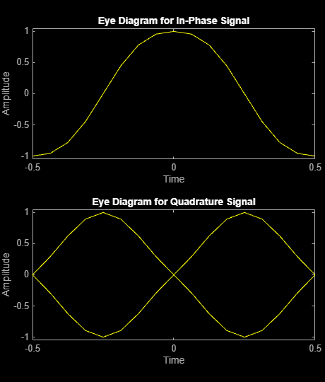
Generate random bit data and apply GFSK modulation. Plot the eye diagram of the modulated signal traces.
numSym = 100; x = randi([0 1],numSym*gfskMod.SamplesPerSymbol,1); y = gfskMod(x); eyediagram(y,16)

Demodulate the GFSK-modulated data. To verify that the demodulated signal data is equal to the original data, account for the delay introduced by the Gaussian filtering in the GFSK modulation and demodulation processes.
z = gfskDemod(y); delay = finddelay(x,z); isequal(x(1:end-delay),z(delay+1:end))
ans = logical
1
More About
When you set BitOutput to false:
The object outputs an integer column vector of length equal to N/NSPS. The output values are odd integers in the range [–(M–1), (M–1)].
You can set the
OutputDataTypeproperty to'double','int8','int16', or'int32'.
When you set BitOutput to true:
The object outputs a binary column vector of length equal to k×(N/NSPS).
In bit output mode, the object follows this process:
Map each demodulated symbol to an odd integer L in the range [–(M–1), (M–1)].
Map L to the nonnegative integer (L + M–1)/2.
Map each nonnegative integer to a k-length binary word using binary-coded ordering or Gray-coded ordering, as specified by the
SymbolMappingproperty.
You can set the
OutputDataTypeproperty to'double','single','logical','int8','int16','int32','uint8','uint16', or'uint32'.
N is the number of input baseband modulated symbols in the input signal (specifically, the length of the input signal).
NSPS represents the value of the
SamplesPerSymbol property.
M is the modulation order, as specified by the
ModulationOrder property. The modulation order,
M = 2k
specifies the number of points in the symbol alphabet, where k is a
positive integer indicating the number of bits per symbol.
The traceback depth, D, is the number of trellis branches used to construct each traceback path in the trellis description of the modulation scheme for demodulation using the Viterbi algorithm.
Determine the optimal setting for traceback depth by calculating the minimum squared Euclidean distance. Alternatively, you can use a common heuristic based on the number of states. Specifically, the five-times-the-constraint-length rule, which approximates the traceback depth as D=5log2(numStates).
For a binary raised cosine pulse shape with a pulse length of 3 and h=2/3, applying this rule D=5log2(3×22) ~ 18 gives a result that is close to the optimum value of 20.
The Viterbi algorithm processing results in a delay preceding the first meaningful demodulated value in the output.
The length of the delay vector, which consists of zero-valued symbols prepended to the
output signal, equals the value of the TracebackDepth property.
Algorithms
CPM demodulation processing consists of a correlator followed by a maximum-likelihood sequence estimation (MLSE) detector that searches the paths through the state trellis for the minimum Euclidean distance path. When the modulation index is rational (h = m / p), a finite number of phase states exist in the symbol. The implementation uses the Viterbi algorithm to perform MLSE detection. The input to the demodulator is a baseband representation of the modulated signal.
{hi} is a sequence of modulation indices that moves cyclically through a set of indices {h0, h1, h2, …,hH-1}.
hi = mi / pi is the modulation index in proper rational form.
mi is the numerator of the modulation index.
pi is the denominator of the modulation index.
mi and pi are relatively prime positive numbers.
The least common multiple (LCM) of {p0, p1, p2, …,pH-1} is denoted as p.
hi= m'i / p.
{hi} determines the number of phase states,
and affects the number of trellis states,
numStates = numPhaseStates×M(L–1),
L is the pulse length.
M is the modulation order.
Continuous phase modulation includes a convolutional encoder, a symbol mapper, and a modulator.
The output of the modulator is a baseband representation of the modulated signal:
where:
{αi} is a sequence of M-ary data symbols selected from the alphabet ±1, ±3, ±(M–1).
M must have the form 2k for some positive integer k, where M is the modulation order and specifies the size of the symbol alphabet.
{hi} is a sequence of modulation indices. hi moves cyclically through a set of indices {h0, h1, h2, ..., hH-1}.
When H=1, only one modulation index exists, h0, which is denoted as h. The phase shift over a symbol is π × h.
When hi varies from interval to interval, the modulator operates in multi-h. To ensure a finite number of phase states, hi must be a rational number.
The CPM method uses pulse shaping to smooth the phase transitions of the modulated signal. The function q(t) is the phase response obtained from the frequency pulse, g(t), through this relation: .
The specified frequency pulse shape corresponds to these pulse shape expressions for g(t).
| Pulse Shape | Expression |
|---|---|
| Rectangular | |
| Raised cosine | |
| Spectral raised cosine | |
| Gaussian | |
| Tamed FM (tamed frequency modulation) |
Lmain is the main lobe pulse duration in symbol intervals.
β is the roll-off factor of the spectral raised cosine.
Bb is the product of the bandwidth and the Gaussian pulse.
The duration of the pulse, LT, is the pulse length in symbol intervals. As defined by the expressions, the spectral raised cosine, Gaussian, and tamed FM pulse shapes have infinite length. For all practical purposes, LT specifies the truncated finite length.
T is the symbol durations.
Q(t) is the complementary cumulative distribution function.
For more information on pulse shape filtering, see [1].
The demodulator uses a trellis representation of CPM. It offers demodulation by
Hard decision — The demodulator generates hard decision (0s and 1s) using the Viterbi algorithm.
The Viterbi algorithm finds the most likely sequence and instead of maximizing the likelihood function for each bit it estimates several bits at once as described in [1].
Soft decision — The demodulator generates soft decision log-likelihood ratios (positive values for 0s and negative values for 1s) using the maximum log maximum a-posteriori probability (max-log-MAP) algorithm.
The forward and backward path metric calculations implement the BCJR algorithm with a sliding window. The BCJR algorithm produces a soft estimate for each bit by considering the incoming bits as a maximum a- posteriori probability (MAP) detection problem as described in [2] and [3] and uses max(ai) for the logarithmic approximation.
This equation shows the branch metric calculation:
yk is the kth received symbol.
xk is one of the possible kth transmitted symbols.
s is the current state of the branch metric.
s' is the previous state of the branch metric.
σ is the noise variance.
References
[1] Anderson, John B., Tor Aulin, and Carl-Erik Sundberg. Digital Phase Modulation. New York: Plenum Press, 1986.
[2] Benedetto, S., G. Montorsi, D. Divsalar, and F. Pollara. "A Soft-Input Soft-Output Maximum A Posterior (MAP) Module to Decode Parallel and Serial Concatenated Codes." Jet Propulsion Lab TDA Progress Report (November 1996): 42–127.
[3] Viterbi, A.J. “An Intuitive Justification and a Simplified Implementation of the MAP Decoder for Convolutional Codes.” IEEE® Journal on Selected Areas in Communications 16, no. 2 (February 1998): 260–64. https://doi.org/10.1109/49.661114.
Extended Capabilities
Usage notes and limitations:
See System Objects in MATLAB Code Generation (MATLAB Coder).
Version History
Introduced in R2012aWhen you set DecisionMethod to
'Approximate log-likelihood ratio', the demodulator generates soft
decision log-likelihood ratios (positive values for 0s and negative values for 1s) using the
maximum log maximum a-posteriori probability (max-log-MAP) algorithm.
This support enables you to vary the length of input signal each time you call the
object. For more information, see input signal X.
See Also
Functions
Objects
comm.CPFSKModulator|comm.CPFSKDemodulator|comm.GMSKModulator|comm.GMSKDemodulator|comm.MSKModulator|comm.MSKDemodulator|comm.CPMModulator
Blocks
MATLAB Command
You clicked a link that corresponds to this MATLAB command:
Run the command by entering it in the MATLAB Command Window. Web browsers do not support MATLAB commands.
Seleccione un país/idioma
Seleccione un país/idioma para obtener contenido traducido, si está disponible, y ver eventos y ofertas de productos y servicios locales. Según su ubicación geográfica, recomendamos que seleccione: .
También puede seleccionar uno de estos países/idiomas:
Cómo obtener el mejor rendimiento
Seleccione China (en idioma chino o inglés) para obtener el mejor rendimiento. Los sitios web de otros países no están optimizados para ser accedidos desde su ubicación geográfica.
América
- América Latina (Español)
- Canada (English)
- United States (English)
Europa
- Belgium (English)
- Denmark (English)
- Deutschland (Deutsch)
- España (Español)
- Finland (English)
- France (Français)
- Ireland (English)
- Italia (Italiano)
- Luxembourg (English)
- Netherlands (English)
- Norway (English)
- Österreich (Deutsch)
- Portugal (English)
- Sweden (English)
- Switzerland
- United Kingdom (English)