Rectangular QAM Demodulator Baseband
Demodulate rectangular-QAM-modulated data

Libraries:
Communications Toolbox /
Modulation /
Digital Baseband Modulation /
AM
Communications Toolbox HDL Support /
Modulation /
AM
Description
The Rectangular QAM Demodulator Baseband block demodulates a signal that was modulated using M-ary quadrature amplitude modulation with a constellation on a rectangular lattice.
Note
All values of power assume a nominal impedance of 1 ohm.
Examples
Modulate and demodulate a noisy QAM signal.
Use the Open model button to open the QAM demodulation model.
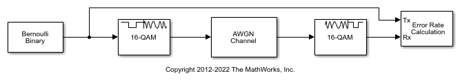
Run the simulation. The results are saved to the base workspace, where the variable ErrorVec is a 1-by-3 row vector. The BER is found in the first element.
Display the error statistics. For the Eb/No provided, 2 dB, the resultant BER is approximately 0.1. Your results may vary slightly.
ans =

    0.0947
Increase the Eb/No to 4 dB. Rerun the simulation, and observe that the BER has decreased.
ans =

    0.0139
Ports
Input
Output
Parameters
Block Characteristics
More About
The Data Type Assistant helps you set data
attributes. To use the Data Type Assistant, click ![]() . For more information, see Specify Data Types Using Data Type Assistant (Simulink).
. For more information, see Specify Data Types Using Data Type Assistant (Simulink).
Algorithms
For algorithm considerations, see Hard- vs. Soft-Decision Demodulation.
The demodulator algorithm maps received input signal constellation values to M-ary integer I and Q symbol indices in the range [0, ] and then maps these demodulated symbol indices to formatted output values. M is the M-ary number parameter value.
The integer symbol index computation is performed by first derotating and scaling the complex input signal constellation (possibly with noise) by a derotate factor and denormalization factor, respectively. These factors are derived from the Phase offset (rad), Normalization method, and related parameters. These derotated and denormalized values are added to to translate them into an approximate range of [0, (2×()+N)]. N is the added noise value. The resulting values are then rescaled via a divide-by-two (or, equivalently, a right-shift by one bit for fixed-point operation) to obtain a range of approximately [0, ( + N)] for I and Q. The noisy index values are rounded to the nearest integer and clipped, via saturation, and then mapped to integer symbol values in the range [0, M – 1]. Finally, based on other block parameters, the integer index is mapped to a symbol value that gets formatted and cast to the selected Output data type.
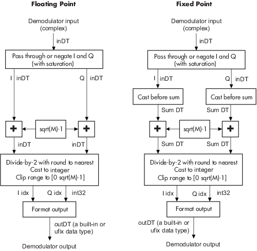
These figures signal flow diagrams for floating-point and fixed-point algorithm operation.
The floating-point diagrams apply when the input signal data type is
double or single. The fixed-point diagrams
apply when the input signal is a signed fixed-point data type. The diagram is
simplified when Phase offset (rad) is a multiple of π/2 or
the derived denormalization factor is 1.
Signal-Flow Diagrams with Trivial Phase Offset and Denormalization Factor Equal to 1
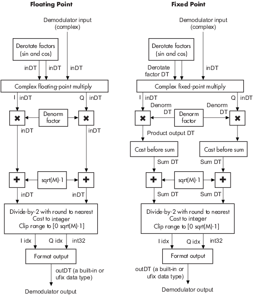
Signal-Flow Diagrams with Nontrivial Phase Offset and Nonunity Denormalization Factor
References
[1] Smith, J. G. "Odd-Bit Quadrature Amplitude-Shift Keying." IEEE® Transactions on Communications 23, no. 3 (March 1975): 385–89.
Extended Capabilities
Version History
Introduced before R2006a