Design and Analysis of a Digital Down Converter
This example shows how to use the digital down converter (DDC) System object™ to emulate the TI Graychip 4016 digital down converter in a simple manner. We base the example on a comparison with the GSM Digital Down Converter in Simulink example. We show how the DDC System object can be used to design and analyze the decimation filters and to quickly explore different design options that meet various passband and stopband frequency and attenuation specifications. This example requires a Fixed-Point Designer™ license.
if ~isfixptinstalled
    error(message('dsp:dspDigitalDownConverterDesign:noFixptTbx'));
end
Introduction
The GSM Digital Down Converter in Simulink example presents the steps required to emulate the TI Graychip 4016 digital down converter that brings a passband signal centered at 14.44 MHz to baseband, and down samples the signal by a factor of 256 to bring the input sample rate of 69.333 MHz down to 270.83 KHz. In that example you go through the following steps:
1) Design a numerically controlled oscillator to generate a mixer frequency of 14.44 MHz.
2) Load a pre-defined set of coefficients to generate a CIC decimator filter, a CIC compensator filter, and an FIR filter with a passband frequency of 80 KHz.
3) Frequency down convert a GSM signal (simulated as a complex exponential) and down sample the down converted output with the cascade of decimation filters.
4) Perform data casting to obtain the desired fixed-point data types across the different down converter sections.
The GSM Digital Down Converter in Simulink example also creates an FIR rate converter to resample the data at the output of the third filter stage. The DDC System object does not contain a rate converter; therefore, this example does not include implementing one.
This example shows how to use the DDC System object to design the set of decimation filters. It also shows how the DDC object achieves the down conversion process with fewer and simpler steps.
The following DDC System object block diagram contains the data types at each stage and the data rates for the example at hand. You control the input data type of the filters using the FiltersInputDataType and CustomFiltersInputDataType properties. You control the output data type using the OutputDataType and CustomOutputDataType properties.

Defining the DigitalDownConverter System Object
Create a DDC System object. Set the input sample rate of the object to 69.333 mega samples per second (MSPS), and the decimation factor to 256 to achieve an output sample rate of 270.83 KHz. The DDC object automatically factors the decimation value so that the CIC filter decimates by 64, the CIC compensator decimates by 2, and the third stage filter decimates by 2.
ddc = dsp.DigitalDownConverter(SampleRate=69.333e6, ...
                                DecimationFactor=256);
Decimation Filter Design
The GSM Digital Down Converter in Simulink example uses a predefined set of filter coefficients to generate two FIR decimators and a CIC decimator System object. Designing decimation filters so that their cascade response meets a given set of passband and stopband attenuation and frequency specifications can be a cumbersome process where you have to choose the correct combination of passband and stopband frequencies for each filter stage. Choosing stopband frequencies properly ensures lower order filter designs.
The DDC object automatically designs the decimation filters based on a set of passband and stopband attenuation and frequency specifications.
Minimum Order Filter Designs
The DDC object obtains minimum order decimation filter designs with the passband and stopband attenuation and frequency specifications you provide. Set the MinimumOrderDesign property to true to obtain minimum order filter designs.
ddc.MinimumOrderDesign = true;
The down converter processes a GSM signal with a double-sided bandwidth of 160 KHz. Set the Bandwidth property of the DDC object to 160 KHz so that the passband frequency of the decimation filter cascade equals 160e3/2 = 80 KHz.
Set the StopbandFrequencySource property to 'Auto' so that the DDC object sets the cutoff frequency of the cascade response approximately at the output Nyquist rate, i.e. at 270.83e3/2 = 135.4 KHz, and the stopband frequency at 2Fc-Fpass = 2*135.4e3 - 160e3/2 = 190.8 KHz, where Fc is the cutoff frequency and Fpass is the passband frequency. When you set StopbandFrequencySource to 'Auto', the DDC object relaxes the stopband frequency as much as possible to obtain the lowest filter orders at the cost of allowing some aliasing energy in the transition band of the cascade response. This design tradeoff is convenient when your priority is to minimize filter orders.
ddc.Bandwidth = 160e3; % Passband frequency equal to 80 KHz
ddc.StopbandFrequencySource = 'Auto'; % Allow aliasing in transition band
Finally, set a stopband attenuation of 55 dB and a passband ripple of 0.04 dB.
ddc.StopbandAttenuation = 55;
ddc.PassbandRipple = .04;
You can analyze the response of the cascade of decimation filters by calling the visualize method of the DDC object. Specify a fixed-point arithmetic so that the DDC object quantizes the filter coefficients to an optimum number of bits that allow the cascade response to meet the stopband attenuation specifications.
fvt = visualize(ddc,Arithmetic='fixed-point');
Get the designed filter orders and the coefficient word lengths for the CIC compensator and third stage FIR design.
ddcFilters = getFilters(ddc,Arithmetic='fixed-point');
n = getFilterOrders(ddc);

CICCompensatorOrder = n.SecondFilterOrder %#ok<NASGU>
CICCompensatorOrder =
12
ThirdStageFIROrder = n.ThirdFilterOrder %#ok<NASGU> ThirdStageFIROrder = 18
CICCompensatorCoefficientsWordLength = ...
    ddcFilters.SecondFilterStage.CustomCoefficientsDataType.WordLength
CICCompensatorCoefficientsWordLength = 11
ThirdStageFIRWordLength = ...
    ddcFilters.ThirdFilterStage.CustomCoefficientsDataType.WordLength
ThirdStageFIRWordLength = 11
If aliasing in the transition band is not acceptable, set the stopband frequency to an arbitrary value by setting the StopbandFrequencySource property to 'Property'. Obtain a narrower transition band by setting the stopband frequency to 128 KHz at the expense of a larger third stage filter order.
ddc.StopbandFrequencySource = 'Property';
ddc.StopbandFrequency = 128e3;

close(fvt)
fvt = visualize(ddc,Arithmetic='fixed-point');
n = getFilterOrders(ddc);
CICCompensatorOrder = n.SecondFilterOrder
CICCompensatorOrder =
10
ThirdStageFIROrder = n.ThirdFilterOrder
ThirdStageFIROrder =
34
Visualize the response of each individual filter stage and of the overall cascade using the visualize method of the DDC object.
close(fvt)
fvt = visualize(ddc,Arithmetic='fixed-point');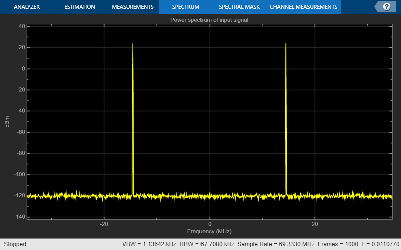
Controlling the Filter Orders
There are cases when filter orders are the main design constraint. You use the DDC object to design decimation filters with a specified order by setting the MinimumOrderDesign property to false. You can still specify the required passband and stopband frequencies of the cascade response. Note however that the stopband attenuation and ripple are now controlled by the order of the filters and not by property values.
Oscillator Design
The DDC object designs a numerically controlled oscillator based on a small set of parameters. Set the Oscillator property to 'NCO' to chose a numerically controlled oscillator. Use 32 accumulator bits, and 18 quantized accumulator bits. Set the center frequency to 14.44 MHz and chose 14 dither bits.
ddc.Oscillator = 'NCO';
ddc.CenterFrequency = 14.44e6;
ddc.NumAccumulatorBits = 32;
ddc.NumQuantizedAccumulatorBits = 18;
ddc.NumDitherBits = 14;
Fixed-Point Settings
You can set different properties on the DDC object to control the fixed-point data types along the down conversion path.
Cast the word and fraction lengths at the input of each filter to 20 and 19 bits respectively by setting the CustomFiltersInputDataType property to numerictype([],20,19). Note that the DDC object scales the data at the output of the CIC decimator. The fact that this scaling is not done in the GSM Digital Down Converter in Simulink example explains the difference in the fraction length values chosen in each example.
Set the output data type to have a word length of 24 bits and a fraction length of 23 bits.
ddc.FiltersInputDataType = 'Custom';
ddc.CustomFiltersInputDataType = numerictype([],20,19);
ddc.OutputDataType = 'Custom';
ddc.CustomOutputDataType = numerictype([],24,23);
Processing Loop
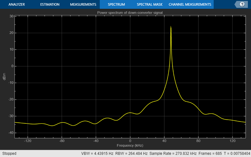
Initialize a sine wave generator input_source to simulate a GSM source. Initialize a buffer gsmsig to cast the input signal data type to 19 bits word length and 18 bits fraction length. Configure figures for plotting spectral estimates of signals.
Fs = 69.333e6;
FrameSize = 768;
input_source = dsp.SineWave(Frequency=14.44e6+48e3,SampleRate=Fs,...
                            PhaseOffset=0,SamplesPerFrame=FrameSize);

gsmsig = fi(zeros(FrameSize,1),true,19,18);

inputSpectrum = spectrumAnalyzer( ...
                    SampleRate=input_source.SampleRate, ...
                    Title='Power spectrum of input signal');

outputSpectrum = spectrumAnalyzer( ...
                    SampleRate=input_source.SampleRate/ddc.DecimationFactor, ...
                    Title='Power spectrum of down-converter signal');
Next, run the main simulation loop.
for ii = 1:1000
    % Sample a GSM signal with a word length of 19 bits and a fraction length
    % of 18 bits.
    gsmsig(:) = input_source();

    % Down convert GSM signal
    downConvertedSig = ddc(gsmsig);

    % Frequency domain plots
    inputSpectrum(gsmsig);
    outputSpectrum(downConvertedSig);
end

% Release objects
release(input_source)
release(ddc)
release(inputSpectrum)
release(outputSpectrum);

Notice the simplification of steps required to down convert a signal when compared to the GSM Digital Down Converter in Simulink example.
Conclusion
In this example, you compared the steps required to design a digital down converter as shown in the GSM Digital Down Converter in Simulink example with the steps required when using a DDC System object. The DDC object allows you to obtain down converter designs in one simple step. It provides tools to design decimation filters that meet passband frequency, passband ripple, stopband frequency, and stopband attenuation specifications. The DDC object also provides convenient tools to visualize and analyze the decimation filter responses.
Further Exploration
You can use the dsp.DigitalUpConverter System object to design a digital up converter system.