Main Content

dsp.DigitalUpConverter

Interpolate digital signal and translate it from baseband to IF band

Description

The dsp.DigitalUpConverter System object™ interpolates a digital signal, and translates it from baseband to intermediate frequency (IF) band.

To digitally upconvert the input signal:

  1. Create the dsp.DigitalUpConverter object and set its properties.

  2. Call the object with arguments, as if it were a function.

To learn more about how System objects work, see What Are System Objects?

This object supports C/C++ code generation and SIMD code generation under certain conditions. For more information, see Code Generation.

Creation

Description

upConv = dsp.DigitalUpConverter returns a digital up-converter (DUC) System object, upConv.

example

upConv = dsp.DigitalUpConverter(Name,Value) returns a DUC System object with the specified property Name set to the specified value Value. You can specify one or more name-value pair arguments in any order as (Name1,Value1,...,NameN,ValueN). Enclose each property name in single quotes. For example, create an object that upsamples the input signal by a factor of 20, using a filter with the specified qualities.

upConv = dsp.DigitalUpConverter('InterpolationFactor',20,...
'SampleRate',Fs,...
'Bandwidth',2e3,...
'StopbandAttenuation',55,...
'PassbandRipple',0.2,...
'CenterFrequency',50e3);

Properties

expand all

Unless otherwise indicated, properties are nontunable, which means you cannot change their values after calling the object. Objects lock when you call them, and the release function unlocks them.

If a property is tunable, you can change its value at any time.

For more information on changing property values, see System Design in MATLAB Using System Objects.

Set this property to a positive scalar value. The value of this property multiplied by the total interpolation factor must be greater than or equal to twice the value of the CenterFrequency property.

Data Types: single | double

Interpolation factor, specified as a positive integer, or a 1-by-2 or 1-by-3 vector of positive integers.

When you set this property to a scalar the object automatically chooses the interpolation factors for each of the three filtering stages.

When you set this property to a 1-by-2 vector, the object bypasses the first filter stage and sets the interpolation factor of the second and third filtering stages to the values in the first and second vector elements, respectively. Both elements of this InterpolationFactor vector must be greater than 1.

When you set this property to a 1-by-3 vector, the ith element of the vector specifies the interpolation factor for the ith filtering stage. The second and third elements of this InterpolationFactor vector must be greater than 1 and the first element must equal 1 or 2.

Data Types: double

Minimum order filter design, specified as true or false.

When you set this property to true, the object designs filters with the minimum order that meets the passband ripple, stopband attenuation, passband frequency, and stopband frequency specifications that you set using the PassbandRipple, StopbandAttenuation, Bandwidth, StopbandFrequencySource, and StopbandFrequency properties.

When you set this property to false, the object designs filters with orders that you specify in the FirstFilterOrder, SecondFilterOrder, and NumCICSections properties. The filter designs meet the passband and stopband frequency specifications that you set using the Bandwidth, StopbandFrequencySource, and StopbandFrequency properties.

Data Types: logical

Order of CIC compensation filter stage, specified as a positive integer.

Dependencies

To enable this property, set the MinimumOrderDesign property to false.

Data Types: double

Order of first filter stage, specified as a positive even integer.

Dependencies

To enable this property, set the MinimumOrderDesign property to false. When you set the InterpolationFactor property to a 1-by-2 vector, the object ignores the FirstFilterOrder property, because the first filter stage is bypassed.

Data Types: double

Number of sections of CIC interpolator, specified as a positive integer.

Dependencies

To enable this property, set the MinimumOrderDesign property to false.

Data Types: double

Two-sided bandwidth of input signal in Hz, specified as a positive integer. The object sets the passband frequency of the cascade of filters to half of the value that you specify in this Bandwidth property.

Data Types: double

Source of stopband frequency, specified as Auto or Property. When you set this property to Auto, the object places the cutoff frequency of the cascade filter response at approximately Fc = SampleRate/2 Hz and computes the stopband frequency as Fstop = Fc + TW/2. TW is the transition bandwidth of the cascade response, computed as 2×(FcFp). Fp is the passband frequency computed by Bandwidth/2.

Stopband frequency in Hz, specified as a positive scalar.

Dependencies

To enable this property, set the StopbandFrequencySource property to Property.

Data Types: double

Passband ripple of cascade response in dB, specified as a positive scalar. When you set the MinimumOrderDesign property to true, the object designs the filters so that the cascade response meets the passband ripple that you specify in this PassbandRipple property.

Dependencies

To enable this property, set the MinimumOrderDesign property to true.

Data Types: double

Stopband attenuation of cascade response in dB, specified as a positive scalar. When you set the MinimumOrderDesign property to true, the object designs the filters so that the cascade response meets the stopband attenuation that you specify in this StopbandAttenuation property.

Dependencies

To enable this property, set the MinimumOrderDesign property to true.

Data Types: double

Type of oscillator, specified as Sine wave or NCO. When you set this property to Sine wave, the object frequency-upconverts the output of the interpolation filter cascade by using a complex exponential signal obtained from samples of a sinusoidal trigonometric function. When you set this property to NCO, the object frequency-upconverts the output by using a complex exponential obtained from a numerically controlled oscillator (NCO).

Center frequency of output signal in Hz, specified as a positive scalar. The value of this property must be less than or equal to half the product of the SampleRate property and the total interpolation factor. The object up converts the input signal so that the output spectrum centers at this frequency you specify in the CenterFrequency property.

Data Types: double

NCO Properties

Number of NCO accumulator bits, specified as an integer in the range [1, 128]. For more details, see the dsp.NCO System object.

Dependencies

To enable this property, set the Oscillator property to NCO.

Data Types: double

Number of NCO accumulator bits, specified as an integer in the range [1, 128]. The value you specify for this property must be less than the value you specify in the NumAccumulatorBits property. For more details, see the dsp.NCO System object.

Dependencies

To enable this property, set the Oscillator property to NCO.

Data Types: double

Dither control for NCO, specified as true or false. When you set this property to true, the object uses the number of dither bits specified in the NumDitherBits property when applying dither to the NCO signal. When this property is false, the NCO does not apply dither to the signal. For more details, see the dsp.NCO System object.

Dependencies

To enable this property, set the Oscillator property to NCO.

Data Types: logical

Number of NCO dither bits, specified as a positive integer scalar smaller than the number of accumulator bits that you specify in the NumAccumulatorBits property. For more details, see the dsp.NCO System object.

Dependencies

To enable this property, set the Oscillator property to NCO and the Dither property to true.

Data Types: double

Fixed-Point Properties

Data type at the output of the first (if it has not been bypassed), second, and third filter stages, specified as Same as input or Custom. The object casts the data at the output of each filter stage according to the value you set in this property. For the CIC stage, the casting is done after the signal is scaled by the normalization factor.

Fixed-point data type at output of each filter stage, specified as a scaled numerictype (Fixed-Point Designer) object with the Signedness property set to Auto.

Dependencies

To enable this property, set the FiltersOutputDataType property to Custom.

Data type of output, specified as Same as input or Custom.

Fixed-point data type of output, specified as a scaled numerictype object the Signedness property set to Auto.

Dependencies

To enable this property, set the OutputDataType property to Custom.

Usage

Description

example

y = upConv(x)returns an upsampled and frequency-upconverted signal y, for a real or complex input column vector x.

Input Arguments

expand all

Input signal, specified as a column vector of real or complex values.

When the data type of x is double or single, the data type of y is the same as that of x. When the data type of x is of a fixed-point type, the data type of y is defined by the OutputDataType property.

Data Types: single | double | int8 | int16 | int32 | int64 | fi
Complex Number Support: Yes

Output Arguments

expand all

Upconverted and upsampled signal, returned as a column vector. The length of y is equal to the length of x multiplied by the value in the InterpolationFactor property. When the data type of x is double or single, the data type of y is the same as that of x. When the data type of x is of a fixed-point type, the data type of y is defined by the OutputDataType property.

Data Types: single | double | int8 | int16 | int32 | int64 | fi

Object Functions

To use an object function, specify the System object as the first input argument. For example, to release system resources of a System object named obj, use this syntax:

release(obj)

expand all

getInterpolationFactorsGet interpolation factors of each filter stage of digital upconverter
getFilterOrdersGet orders of digital down converter or digital up converter filter cascade
getFiltersGet handles to digital down converter or digital up converter filter cascade objects
fvtoolVisualize frequency response of digital down converter or digital up converter filter cascade
groupDelayGroup delay of digital down converter or digital up converter filter cascade
visualizeFilterStagesDisplay response of digital down converter or digital up converter filter cascade
generatehdlGenerate HDL code for quantized DSP filter (requires Filter Design HDL Coder)
stepRun System object algorithm
releaseRelease resources and allow changes to System object property values and input characteristics
resetReset internal states of System object

Examples

collapse all

Create a DUC System object™ that upsamples a 1-kHz sinusoidal signal by a factor of 20 and upconverts it to 50 kHz.

Create a sine wave generator to obtain the 1-kHz sinusoidal signal with a sample rate of 6 kHz.

 Fs = 6e3; % Sample rate
 sine = dsp.SineWave('Frequency',1000,...
     'SampleRate',Fs,...
     'SamplesPerFrame',1024);
 x = sine(); % generate signal

Create a DUC System object. Use minimum order filter designs and set the passband ripple to 0.2 dB and stopband attenuation to 55 dB. Set the double-sided signal bandwidth to 2 kHz.

upConv = dsp.DigitalUpConverter(... 
     'InterpolationFactor',20,...
     'SampleRate',Fs,...
     'Bandwidth',2e3,...
     'StopbandAttenuation',55,...
     'PassbandRipple',0.2,...
     'CenterFrequency',50e3);

Create a spectrum estimator to visualize the signal spectrum before and after upconverting.

window = hamming(floor(length(x)/10));
figure; pwelch(x,window,[],[],Fs,'centered')
title('Spectrum of baseband signal x')

Figure contains an axes object. The axes object with title Spectrum of baseband signal x, xlabel Frequency (kHz), ylabel Power/frequency (dB/Hz) contains an object of type line.

Upconvert the signal and visualize the spectrum.

 xUp = upConv(x); 
 window = hamming(floor(length(xUp)/10));
 figure; 
 pwelch(xUp,window,[],[],20*Fs,'centered')
 title('Spectrum of upconverted signal xUp')

Figure contains an axes object. The axes object with title Spectrum of upconverted signal xUp, xlabel Frequency (kHz), ylabel Power/frequency (dB/Hz) contains an object of type line.

Visualize the response of the interpolation filters.

 visualizeFilterStages(upConv)

Figure Figure 1: Magnitude Response (dB) contains an axes object. The axes object with title Magnitude Response (dB), xlabel Frequency (kHz), ylabel Magnitude (dB) contains 5 objects of type line. These objects represent Halfband interpolator, Interpolation factor = 2, CIC compensator, Interpolation factor = 2, CIC interpolator, Interpolation factor = 5, Cascade response.

More About

expand all

Algorithms

The digital up converter upsamples the input signal using a cascade of three interpolation filters. This algorithm frequency-upconverts the upsampled signal by multiplying it with a complex exponential that has the specified center frequency. In this case, the filter cascade consists of an FIR interpolation stage, a second stage for CIC compensation, and a CIC interpolator. The block diagram shows the architecture of the digital up converter.

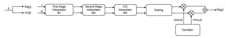
The scaling section normalizes the CIC gain and the oscillator power. It can also contain a correction factor to achieve the desired ripple specification. Depending on how you set the interpolation factor, the block bypasses the first filter stage. When the input data type is floating point, the algorithm implements an N-section CIC interpolation filter as a FIR filter with a response that corresponds to a cascade of N boxcar filters. The algorithm emulates a CIC filter with an FIR filter so that you can run simulations with floating-point data. When the input data type is a fixed-point type, the algorithm implements a true CIC filter with actual comb and integrator sections.

This block diagram represents the DUC arithmetic with floating-point inputs.

For details about fixed-point operation, see Fixed Point.

Extended Capabilities

Version History

Introduced in R2012a