Generate HDL for Preconfigured Algorithm with DSP HDL IP Designer App
The DSP HDL IP Designer app lets you select and configure hardware-optimized algorithms and generate HDL code for those algorithms without having to create a Simulink® model or MATLAB® script.
Alternatively, you can design your algorithm outside the app and then open the app by
providing a preconfigured System object™ from the command line by calling
dsphdlIPDesigner(ObjVariable). You can also design a filter using the
Filter Designer (Signal Processing Toolbox) app, then go to the Export menu, and select
Export to DSP HDL IP Designer to open the DSP HDL IP
Designer app.
When you use a DSP HDL Toolbox™ System object, the app copies all the properties of the object into the app. When you use a DSP System Toolbox™ System object, or you open the app from Filter Designer (Signal Processing Toolbox), the app copies the filter structure, filter coefficients, and coefficient data type from your specified algorithm.
Once your algorithm is loaded in the app, you can specify input stimulus, configure code generation options, and generate HDL code and testbenches. For an example of calling the app with a System object, see Open App with Preconfigured Algorithm.
Supported Algorithms
You can open the app with any DSP HDL Toolbox System object. For the complete list, see DSP HDL Toolbox System objects.
The app also supports these DSP System Toolbox System objects:
dsp.HighpassFilter— Implemented as a discrete FIR filter or biquad filterdsp.LowpassFilter— Implemented as a discrete FIR filter or biquad filterdsp.CICCompensationDecimator— Implemented as an FIR decimator filterdsp.CICCompensationInterpolator— Implemented as an FIR interpolator filterdsp.DCBlocker— Implemented as a biquad filter
Open App with Preconfigured Algorithm
This example shows how to configure your algorithm by using a System object™ and then open the app to generate HDL code and testbenches for the algorithm. Part one shows how to export a filter designed in the Filter Designer app, part two shows how to open the app with a preconfigured DSP System Toolbox™ filter object, and part three shows how to open the app by using a preconfigured DSP HDL Toolbox™ object.
Part 1: Export from Filter Designer App
This example shows the filter design from the High Performance DC Blocker for FPGA example. The example designs a lowpass filter and then subtracts the low frequency output of the filter from the input signal. Call filterDesigner to open the Filter Designer app. Select a lowpass IIR filter and enter these specifications.
filterOrder = 6;
normalizedBandwidth = 0.001;
passbandRipple = 0.1;
stopbandAtten  = 60;
In the Algorithm section, set Design method to Elliptical. In the Algorithm Options section, clear the Scale SOS coefficients box. Click the Update Filter button and verify the filter response.
In the toolbar, click the Export button and expand the dropdown menu. Select Export to DSP HDL IP Designer.

The DSP HDL IP Designer app opens with a Biquad Filter algorithm configured with the default filter structure, and the coefficients and scale factors designed by the Filter Designer app. You can change the Filter structure parameter to select the hardware implementation of the filter. The default input stimulus for this algorithm is fi(1,16,8) data type.
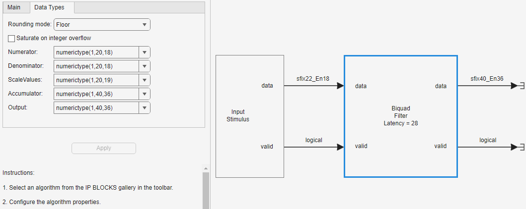
Edit the input stimulus to specify the data type your system requires. To match the DC blocker example linked above, set the input stimulus to fi(1,22,18) data type.
You can also select data types for the filter implementation from the algorithm Data Types tab. This screenshot shows the data types configured the same as the DC Blocker example. For help selecting fixed point data types for an IIR filter, see Choose Data Types for Biquad Filter.
Once you have configured your data types and input data values, you can set HDL code and testbench generation options, and generate HDL code for the algorithm. The generated testbenches apply the custom input data generated by the code in the Input Stimulus block.
Part 2: DSP System Toolbox™ Filter Object
This example shows the lowpass filter design from the Removing High-Frequency Noise from an ECG Signal example.
Design a minimum-order lowpass filter with a passband edge frequency of 200 Hz and a stopband edge frequency of 400 Hz. The desired amplitude of the frequency response and the weights are specified in A and D vectors, respectively. The firgr function takes these specifications and returns filter coefficients. Pass these designed coefficients to the dsp.FIRFilter object.
Fs = 1000;
Fpass = 200;
Fstop = 400;
Dpass = 0.05;
Dstop = 0.0001;
F = [0 Fpass Fstop Fs/2]/(Fs/2);
A = [1 1 0 0];
D = [Dpass Dstop];
b = firgr('minorder',F,A,D);
LP = dsp.FIRFilter('Numerator',b);
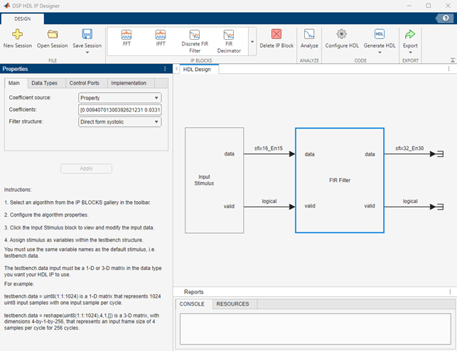
To open the app with your preconfigured algorithm loaded, call the app with the System object as an argument, dsphdlIPDesigner(LP). The app opens with a Discrete FIR Filter algorithm configured with the filter structure, coefficients, and coefficient data type from the object. The filter implements a direct-form systolic architecture, which is a fully parallel filter. You can change the algorithm properties to configure the hardware implementation of the filter.
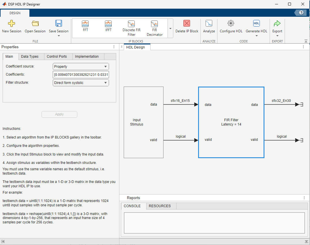
Choose data types for your hardware filter implementation. Consider which data types can represent your coefficients efficiently, and how many resources the filter uses. The app displays the input and output data types on the connecting arrows. The default data type for the filter coefficients is the same as the input data type. On the Data Types tab, you can specify a custom data type for the coefficients or the output data.
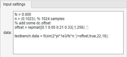
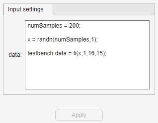
Click the Input Stimulus block to specify an input data vector to set the input data type, and the data values applied in the generated testbenches. The image shows the default input settings. The default input data type is fi(1,16,15), and the generated testbenches apply 200 random data samples to the filter.
You can set the input stimulus to realistic data for your application. For instance, load the app-lowpassECG-ex.mat file to load the same data generation code as the Removing High-Frequency Noise from an ECG Signal example. This code generates an ECG signal and adds high-frequency noise to it.
For more examples of input configuration, see Setting Input Stimulus.
Once you have configured your data types and input data values, you can set HDL code and testbench generation options, and generate HDL code for the algorithm. The generated testbenches apply the custom ECG data generated from the code in the Input Stimulus block.
Part 3: DSP HDL Toolbox NCO Object
This code configures a numerically controlled oscillator (NCO) to generate a sine wave with these specifications:
F0 = 510;     % Target output frequency in Hz
dphi = pi/2;  % Target phase offset
df = 0.05;    % Frequency resolution in Hz
minSFDR = 96; % Spurious free dynamic range(SFDR) in dB
Ts = 1/4000;  % Sample period in seconds
Calculate the number of accumulator bits required for the frequency resolution and the number of quantized accumulator bits needed to satisfy the SFDR requirement. The actual frequency resolution achieved is 1/(Ts*2^Nacc).
Nacc = ceil(log2(1/(df*Ts)));
Nqacc = ceil((minSFDR-12)/6);
Calculate the phase increment and offset to achieve the target frequency and offset.
phIncr = round(F0*Ts*2^Nacc);
phOffset = 2^Nacc*dphi/(2*pi);
Create a dsphdl.NCO System object with properties set to the calculated settings.
nco510 = dsphdl.NCO(PhaseIncrementSource='Property', ...
    PhaseIncrement=phIncr, ...
    PhaseOffset=phOffset, ...
    NumDitherBits=4, ...
    NumQuantizerAccumulatorBits=Nqacc, ...
    AccumulatorWL=Nacc);
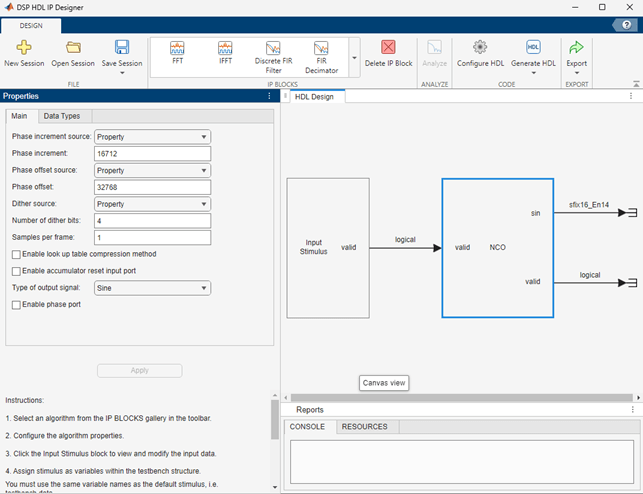
To open the app with your preconfigured algorithm loaded, call the app with the System object as an argument, dsphdlIPDesigner(nco510).
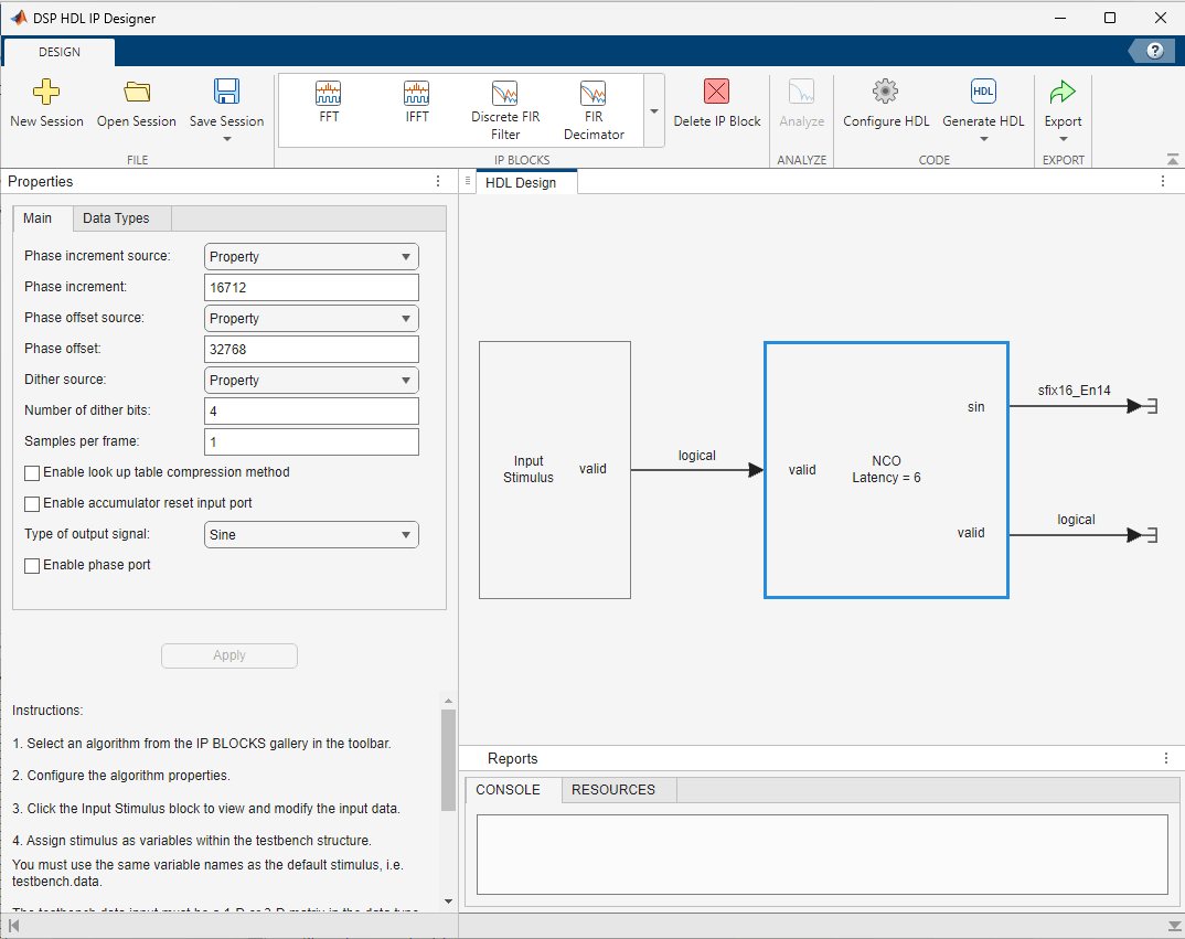
This configuration of the NCO object has no input stimulus to configure. You can set HDL code and testbench generation options, and generate HDL code for the algorithm.