Rapid Prototyping Model Functions
Rapid prototyping code defines the following functions that interface with the main
program (main.c or main.cpp):
Model(): The model registration function. This function initializes the work areas (for example, allocating and setting pointers to various data structures) used by the model. The model registration function calls theMdlInitializeSizesandMdlInitializeSampleTimesfunctions. These two functions are very similar to the S-functionmdlInitializeSizesandmdlInitializeSampleTimesmethods.MdlStart(void): After the model registration functionsMdlInitializeSizesandMdlInitializeSampleTimesexecute, the main program starts execution by callingMdlStart. This routine is called once at startup.The function
MdlStarthas four basic sections:Code to initialize the states for each block in the root model that has states. A subroutine call is made to the “initialize states” routines of conditionally executed subsystems.
Code generated by the one-time initialization (start) function for each block in the model.
Code to enable the blocks in the root model that have enable methods, and the blocks inside triggered or function-call subsystems residing in the root model. Simulink® blocks can have enable and disable methods. An enable method is called just before a block starts executing, and the disable method is called just after the block stops executing.
Code for each block in the model whose output value is constant. The block code appears in the
MdlStartfunction only if the block parameters are not tunable in the generated code and if the code generator cannot eliminate the block code through constant folding.
MdlOutputs(int_T tid):MdlOutputsupdates the output of blocks. Thetid(task identifier) parameter identifies the task that in turn maps when to execute blocks based upon their sample time. This routine is invoked by the main program during major and minor time steps. The major time steps are when the main program is taking an actual time step (that is, it is time to execute a specific task). If your model contains continuous states, the minor time steps will be taken. The minor time steps are when the solver is generating integration stages, which are points between major outputs. These integration stages are used to compute the derivatives used in advancing the continuous states.MdlUpdate(int_T tid):MdlUpdateupdates the states and work vector state information (that is, states that are neither continuous nor discrete) saved in work vectors. Thetid(task identifier) parameter identifies the task that in turn indicates which sample times are active, allowing you to conditionally update only states of active blocks. This routine is invoked by the interface after the majorMdlOutputshas been executed. The solver is also called, andmodel_DerivativesMdlTerminate(void):MdlTerminatecontains any block shutdown code.MdlTerminateis called by the interface, as part of the termination of the real-time program.
The contents of the above functions are directly related to the blocks in your model. A Simulink block can be generalized to the following set of equations.
Output y is a function of continuous state
xc, discrete state
xd, and input
u. Each block writes its specific equation in a section of
MdlOutputs.
The discrete states xd are a
function of the current state and input. Each block that has a discrete state updates its
state in MdlUpdate.
The derivatives x are a function of the current input. Each block
that has continuous states provides its derivatives to the solver (for example,
ode5) in
model_Derivatives
The output, y, is generally written to the block I/O structure.
Root-level Outport blocks write to the external outputs structure. The continuous and discrete
states are stored in the states structure. The input, u, can originate
from another block's output, which is located in the block I/O structure, an external input
(located in the external inputs structure), or a state. These structures are defined in the
model.h
The next example shows the general contents of the rapid prototyping style of C code
written to the model.c
This figure shows a flow chart describing the execution of the rapid prototyping generated code.
Rapid Prototyping Execution Flow Chart
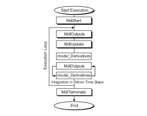
Each block places code in specific Mdl routines according to the
algorithm that it is implementing. Blocks have input, output, parameters, and states, as well
as other general items. For example, in general, block inputs and outputs are written to a
block I/O structure (model_Bmodel_Umodel_XrtGround) if unconnected or grounded. Block outputs can also go to the
external output structure (model_Y
Data View of the Generated Code
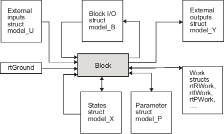
The following list defines the structures shown in the preceding figure:
Block I/O structure (
model_Bmodel_BReusing the entries in the
model_BMaking other entries local variables
See How Generated Code Stores Internal Signal, State, and Parameter Data for more information on these optimizations.
Structure field names are determined either by the block's output signal name (when present) or by the block name and port number when the output signal is left unlabeled.
Block states structures: The continuous states structure (
model_XDWork vector(model_DWork)Block parameters structure (
model_PExternal inputs structure (
model_UExternal outputs structure (
model_YReal work, integer work, and pointer work structures (
model_RWorkmodel_IWorkmodel_PWork