Configure Blocks with Fixed-Point Output
R2026bYou can use fixed-point data types in your Simulink® model to create efficient designs and perform bit-true simulations prior to hardware deployment. Fixed-Point Designer™ helps you meet the data type requirements for your desired hardware target by fine-tuning the data types for the blocks in your system.
To create a fixed-point model, configure Simulink blocks to output fixed-point signals. Simulink blocks that support fixed-point output have parameters that allow you to specify whether a block should output fixed-point signals and, if so, to set the size, scaling, and other attributes of the fixed-point output. These parameters appear on the block parameter dialog box on the Signal Attributes pane or the Data Types pane.

Specify Output Data Type and Scaling
Specify an output data type and scaling for a block using the Output data type parameter. The parameter drop-down list provides these options for specifying the block's output data type:
Rules for inheriting data types
Built-in data types
An expression that evaluates to a data type
A Simulink data type object.
The options for the Output data type parameter vary based on the supported data types for a particular block.
Use fixdt to Specify Output Data Types
You can enter a fixdt function to specify the
Output data type parameter. The
fixdt function allows you to specify floating point and
fixed-point types, and to adjust the scaling of a fixed-point data type. For
binary point scaling, use this syntax to specify a fraction
length.
fixdt(Signed,WordLength,FractionLength)
fixdt(Signed,WordLength,Slope,Bias)
fixdt(Signed,WordLength,SlopeAdjustmentFactor,FixedExponent,Bias)
The table shows examples of binary-point scaled and unscaled data types you
can specify with fixdt.
| Data Type | Description | Examples |
|---|---|---|
| Integers | Integer values have a default binary point located to the right of all bits. |
|
| Fractional Numbers | Fractional numbers are characterized by the position of the binary point.
Both unsigned and signed fractional data types support guard bits, which guard against overflow. |
|
| Fixed-Point Numbers with Unspecified Scaling | Fixed-point numbers with no default scaling. Note Fixed-point numbers with unspecified scaling are only supported for blocks with Output minimum and Output maximum parameters. When scaling is unspecified for these blocks, the software will select a scaling that fits the desired range. |
|
| Slope and Bias Scaled Number | Slope and bias scaled numbers use a linear transformation defined by a slope and a bias. |
|
| Floating-Point Numbers | Single-precision and double-precision floating-point numbers as defined by the IEEE® Standard 754–1985 for Binary Floating-Point Arithmetic. |
|
Use numerictype to Specify Output Data Types
You can enter a numerictype object to specify
the Output data type parameter. Similar to
fixdt, the numerictype object allows
you to specify floating-point and fixed-point types, and to adjust the scaling
of a fixed-point data type. For binary point scaling, use this syntax to specify
a fraction
length.
numerictype(Signed,WordLength,FractionLength)
numerictype(Signed,WordLength,Slope,Bias)
numerictype(Signed,WordLength,SlopeAdjustmentFactor,FixedExponent,Bias)
numerictype("single")Specify Fixed-Point Data Types with the Data Type Assistant
The Data Type Assistant is a graphical interactive tool that helps you specify data types for Simulink blocks and data objects. The assistant appears on block and object dialog boxes. You can access the assistant by clicking the Show data type assistant button located to the right of the Output data type parameter.
To use the Data Type Assistant to specify a fixed-point data
type, set the Mode parameter to Fixed
point. The assistant displays fields to specify the attributes of
a fixed-point data type.

Signedness
Set the fixed-point data to Signed or
Unsigned. Signed data can represent positive and
negative quantities. Unsigned data represents positive values only.
Word Length
Specify the size (in bits) of the word that will hold the quantized integer. Large word sizes represent large quantities with greater precision than small word sizes. Fixed-point word sizes up to 65535 bits are supported for simulation.
Scaling
Specify the method for scaling your fixed-point data to avoid overflow conditions and minimize quantization errors.
| Scaling Mode | Description |
|---|---|
Binary point | If you select this mode, the assistant displays the Fraction length field, specifying the binary point location. Binary points can be positive or negative integers. A positive integer moves the binary point left of the rightmost bit by that amount. For example, an entry of 2 sets the binary point in front of the second bit from the right. A negative integer moves the binary point further right of the rightmost bit by that amount.
See Binary-Point Scaling for more information. |
Slope and bias | If you select this mode, the assistant displays fields for entering the Slope and Bias.
See Slope-Bias Scaling for more information. |
Best precision | If you select this mode, the block scales a constant vector or matrix such that the precision of its elements is maximized. This mode is available only for particular blocks. See Constant Scaling for Best Precision for more information. |

Data type override
When the Mode is Built in or
Fixed point, you can use the Data type
override option to specify whether you want this data type to
inherit or ignore the data type override setting specified for its context, that
is, for the block, Simulink.Signal object or Stateflow® chart in Simulink that is using the signal. The default behavior is
Inherit.
| Data Type Override Mode | Description |
|---|---|
Inherit (default) | Inherits the data type override setting from its
context, that is, from the block,
|
Off | Ignores the data type override setting of its context and uses the fixed-point data type specified for the signal. |
The ability to turn off data type override for an individual data type provides greater control over the data types in your model when you apply data type override. For example, you can use this option to ensure that data types meet the requirements of downstream blocks regardless of the data type override setting.
Calculate Best-Precision Scaling
The Fixed-Point Designer software can automatically calculate best-precision values for
both Binary point and Slope and
bias scaling, based on the values that you specify for other
parameters on the dialog box. The best-precision scaling maximizes precision
within the given bit width constraints.
To calculate best-precision-scaling values automatically, enter values for the Output minimum and Output maximum parameters. Then click Calculate Best-Precision Scaling.
Showing Fixed-Point Details
When you specify a fixed-point data type, you can use the Fixed-point details subpane to see information about the fixed-point data type that is currently displayed in the Data Type Assistant. To see the subpane, click the expander next to Fixed-point details in the Data Type Assistant. The Fixed-point details subpane appears at the bottom of the Data Type Assistant:
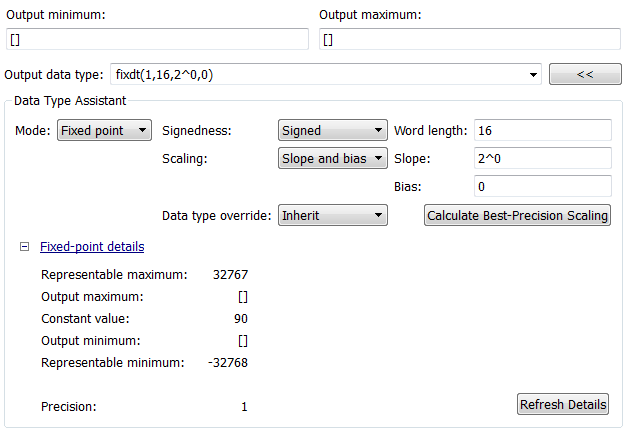
The rows labeled Output minimum and Output
maximum show the same values that appear in the corresponding
Output minimum and Output maximum fields above the Data Type Assistant. The names
of these fields may differ from those shown. For example, a fixed-point block
parameter would show Parameter minimum and
Parameter maximum, and the corresponding
Fixed-point details rows would be labeled
accordingly. See Specify Signal Ranges and Specify Minimum and Maximum Values for Block Parameters for
more information.
The rows labeled Representable minimum, Representable maximum, and Precision always appear. These rows show the minimum value,
maximum value, and precision that can be represented by the fixed-point data
type currently displayed in the Data Type Assistant.
The values displayed by the Fixed-point details subpane do not automatically update if you click Calculate Best-Precision Scaling, or change the range limits, the values that define the fixed-point data type, or anything elsewhere in the model. To update the values shown in the Fixed-point details subpane, click Refresh Details. The Data Type Assistant then updates or recalculates all values and displays the results.
Clicking Refresh Details does not change
anything in the model, it only changes the display. Click OK or Apply to put the
displayed values into effect. If the value of a field cannot be known without
first compiling the model, the Fixed-point
details subpane shows the value as Unknown.
If any errors occur when you click Refresh Details, the Fixed-point details subpane shows an error flag on the left of the applicable row, and a description of the error on the right. For example, the next figure shows two errors:
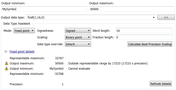
The row labeled Output minimum shows
the error Cannot evaluate because evaluating the expression
MySymbol, specified in the Output
minimum field, did not return an appropriate numeric value. When
an expression does not evaluate successfully, the Fixed-point details subpane displays the unevaluated expression
(truncating to 10 characters if necessary to save space) in place of the
unavailable value.
To correct the error in this case, you would need to define
MySymbol in an accessible workspace to provide an
appropriate numeric value. After you click Refresh
Details, the value of MySymbol appears in
place of its unevaluated text, and the error indicator and error description
disappear.
To correct the error shown for Output maximum, you
would need to decrease Output maximum, increase
Word length, or decrease Fraction length (or some combination of these
changes) sufficiently to allow the fixed-point data type to represent the
maximum value that it could have.
Other values relevant to a particular block can also appear in the Fixed-point details subpane. For example, on a Discrete-Time Integrator block Signal Attributes tab, the subpane can look like this:
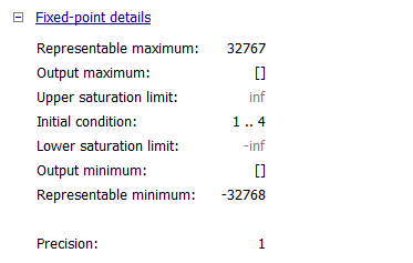
The values displayed for Upper saturation limit and Lower saturation limit are grayed out. This appearance indicates that the corresponding parameters are not currently used by the block. The grayed-out values can be ignored.
To conserve space, Initial condition displays the smallest value and the largest value in the vector or matrix, using ellipsis to represent the other values. The underlying definition of the vector or matrix is unaffected.
Rounding
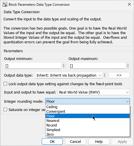
Use the Integer rounding mode parameter to specify how fixed-point numbers are rounded.
The rounding mode determines how numbers are represented within a fixed-point data type when they cannot be represented exactly due to limitations on precision. These rounding modes are supported:
Ceiling— Round toward positive infinity. This mode is equivalent to the MATLAB®ceilfunction.Convergent— Round toward the nearest representable number, with ties rounding to the nearest even integer. Convergent rounding is equivalent to the Fixed-Point Designerconvergentfunction.Floor— Round toward negative infinity. This mode is equivalent to the MATLABfloorfunction.Nearest— Round toward the nearest representable number, with the exact midpoint rounded toward positive infinity. Rounding toward nearest is equivalent to the Fixed-Point Designernearestfunction.Round— Round to the nearest representable number, with ties for positive numbers rounding in the direction of positive infinity and ties for negative numbers rounding in the direction of negative infinity. This mode is equivalent to the Fixed-Point Designerroundfunction.Simplest— Automatically choose between round toward floor and round toward zero to produce generated code that is as efficient as possible.Zero— Round toward zero. This mode is equivalent to the MATLABfixfunction.
For more information on each of these rounding modes, see Rounding Modes.
Overflow Handling
To control how overflow conditions are handled for fixed-point operations, select Saturate on integer overflow.
If this check box is selected, overflows saturate to either the maximum or minimum value represented by the data type. For example, an overflow associated with a signed 8-bit integer can saturate to -128 or 127.
If this check box is not selected, overflows wrap to the appropriate value that is representable by the data type. For example, the number 130 does not fit in a signed 8-bit integer, and would wrap to -126.
Lock the Output Data Type Setting
To lock the output data type setting of a block, select the Lock output data type setting against changes by the fixed-point tools check box.
When locked, the Fixed-Point Tool and automatic scaling script
autofixexp do not change the
output data type setting. Otherwise, the Fixed-Point Tool and
autofixexp script are free to adjust the output data type
setting.
Real-World Values Versus Stored Integer Values
You can configure Data Type Conversion blocks to treat signals as real-world values or as stored integers with the Input and output to have equal parameter.
Real World Value (RWV)- Signals are treated as the real-world values that they represent, accounting for scaling applied to the number. Real-world values are commonly used for high-level system modeling, testing, and validation.Stored Integer (SI)- Signals are treated as the raw integer value stored in memory, without accounting for scaling. Stored integer values are commonly used for modeling hardware that produces integers as output.
For more information about how integers are scaled to store real-world values, see Scaling, Range, and Precision.


