Generate HDL Code from Simulink Model
This example shows how you can generate HDL code for a simple counter model in Simulink®. This model is compatible for HDL code generation. To create this counter model, see Create HDL-Compatible Simulink Model.
Model Templates for HDL Code Generation
You can use templates to model registers, ROM, basic arithmetic operations, complex multipliers, shift registers, and so on.
To choose your template, on the MATLAB® toolstrip, click the ![]() button, and then navigate to the
HDL Coder section. See Use Simulink Templates for HDL Code Generation.
button, and then navigate to the
HDL Coder section. See Use Simulink Templates for HDL Code Generation.
Before generating HDL code, you can check and update the model for HDL compatibility by using the HDL Code Advisor. See Check HDL Compatibility of Simulink Model Using HDL Code Advisor.
Simple Counter Model
This model counts up from zero to a threshold value of 15, then wraps back to zero. You can change the threshold value by changing the value of the Constant block connected to the count_threshold port. The Enable port specifies whether the counter counts upward or holds the previous value. You can change the counter action by changing the value of the Constant block connected to the Enable port. A value of 1 indicates that the counter counts upward. A value of 0 holds the previous count value.

Generate HDL Code
For the counter model, the HDL_DUT subsystem is the DUT. To
generate code for the DUT:
In the Apps tab, select HDL Coder.
Select the DUT Subsystem in your model, and make sure that this Subsystem name appears in the Code for option on the HDL Code tab. To remember the selection, pin this option. Click Generate HDL Code.
By default, HDL Coder™ generates VHDL code in the target hdlsrc
folder.
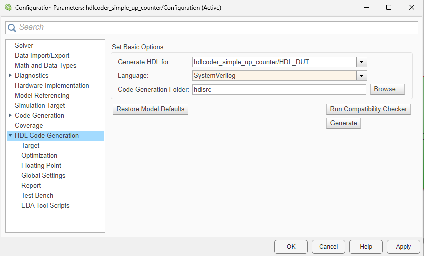
Generate SystemVerilog Code
To generate SystemVerilog code for the counter model:
In the HDL Code tab, click Settings.
In the HDL Code Generation pane, for Language, select
SystemVerilog. Click Apply and then click Generate.
HDL Coder compiles the model before generating code. Depending on model display options such as port data types, the model can change in appearance after code generation. As code generation proceeds, HDL Coder displays progress messages in the MATLAB command line with links to the configuration set and the generated files. To view the files in the MATLAB Editor, click the links.
The process is completed and displays the message:
### HDL Code Generation Complete.
View HDL Code Generation Files
A folder icon for the hdlsrc folder appears in the current
folder. To view the generated code and script files, double-click the
hdlsrc folder, and then double-click the folder that has
the same name as the model for which you generated HDL code.
HDL_DUT.vhd: VHDL® code that contains the entity definition and RTL architecture implementing the counter that you designed. If you generated Verilog or SystemVerilog code, you get aHDL_DUT.vorHDL_DUT.svfile.HDL_DUT_compile.do: Siemens® ModelSim™ compilation script.HDL_DUT_map.txt: Mapping file that maps generated entities or modules in the HDL code to subsystems in the model that generated them. See Trace Code Using the Mapping File.HDL_DUT_report.html: HDL check report displays HDL code generation status and warnings or messages.gm_hdlcoder_simple_up_counter.slx: Generated model that behaviorally represents the HDL code in the Simulink modeling environment.hcv: HDL code view file to display the generated code on the Code View panel in Simulink. To view generated HDL code in Simulink, click View Code on the HDL Coder app.
HDL Coder creates a behavioral model of the HDL code called the
generated model. The generated model name is the same
as the original model and has the prefix gm_. The generated
model is bit-true and
cycle-accurate to the generated HDL code. This
model shows the effect of block implementations
and speed and area optimizations that you specified. See also Introduction to Optimizations in HDL Coder.
To open the generated model for the counter, enter:
gm_hdlcoder_simple_up_counter
For the counter model, as optimizations are disabled, the generated model is identical to the original model.
To view your generated HDL code alongside your model, you can use the Code view. After you generate HDL code for your model, the Code view displays the generated code to the right of your model. To manually open the Code view, open the HDL Coder app. On the Simulink toolstrip click the View Code button. Select the file that you want to display by using the drop-down list at the top of the Code view. You can dock or undock the Code view from the editor and minimize or expand the Code view using the down arrow in the upper right corner of the Code view.
Inspect Generated HDL Code
To identify the mapping between the source model and the generated HDL code more easily, generate a traceability report. Use the report to navigate from a block in your model to the generated code for that block and from the code to a block in your model.
To generate the traceability report:
In the HDL Code tab, click Settings > Report Options.
In the HDL Code Generation > Report pane, select Generate traceability report, and then generate HDL code for the
HDL_DUTsubsystem

After you generate code, the Code Generation Report window opens. HDL Coder writes the code generation report files in the
hdlsrc\html\ folder of the build folder. If you close the
report, you can navigate to this folder to reopen the report.
To navigate from the HDL code to the model, follow either of these workflows:
Use the Code view:
Click the Code view panel on the right that appears after generating HDL code or manually click the View Code button on the Simulink toolstrip of the HDL Coder app.
To navigate from model elements to their generated code, in your model, click a block. The Code view highlights the code for the block and scrolls to the highlighted code lines.

In the Code view, click the line number hyperlink or code comment link to highlight the block that the code line traces to. You can trace lines of code to the model elements from which they were generated.

Use the Code Generation Report:
In the Code Generation Report, navigate to the Traceability Report section, and then click the links in the Code Location section.
Select the hyperlink to a line of code to highlight the corresponding block in your model.
To navigate from a block in your model to the HDL code, select that block, and then click the Navigate to Code button in the Review Results section of the HDL Code tab.

See Navigate Between Simulink Model and HDL Code by Using Traceability and Create and Use Code Generation Reports.
In the Generated Source Files section, if you click the
HDL file HDL_DUT, you see the signals clk,
reset, and clk_enable. These signals
are the clock, reset, and clock enables signals that control the flip-flops on
the target hardware. HDL Coder generates these signals in the code depending on sequential
elements such as Delay blocks that you use in your model. See
Generation of Clock Bundle Signals in HDL Coder.
Validate HDL Behavior Using Validation Model
To validate the behavioral model of the HDL code with your original model, generate a validation model. The validation model contains both the original model and generated model. It compares the outputs of both models by using the test vectors that you provided in the original model.
To generate the validation model:
In the HDL Code tab, click Settings.
In the HDL Code Generation > Global Settings > Model Generation tab, select Validation model, and then generate HDL code for the
HDL_DUTsubsystem.

In the code generation logs, you see a link to the validation model. The
validation model has the same prefix as the generated model and also has the
suffix _vnl. For the counter model, the validation model has
the name gm_hdlcoder_simple_up_counter_vnl.slx. You can find
this model in the same folder as the generated model. To open this model,
enter:
gm_hdlcoder_simple_up_counter_vnl

After you simulate the model, double-click the Compare
subsystem, and then navigate inside the Assert_Out subsystem.
If you open the Scope block, you see that the
err signal has a value of zero, which means that the
generated model output matches the original model.
Verify Generated HDL Code
Before you deploy your design on the target hardware, verify the generated HDL
code. From the hdlsrc folder, navigate to the current working
folder. See Verify Generated HDL Code from Simulink Model.
See Also
makehdl | hdlset_param | hdlsetup