Remove Redundant Logic and Unused Blocks in Generated HDL Code
If your design contains redundant logic or unused blocks, HDL Coder™ removes the blocks, components, or part of the HDL code that does not contribute to the output.
Redundant Logic Considerations
Components that do not contribute to the output in the design are removed during HDL code generation. Removing redundant logic reduces code size and avoids potential synthesis failures with downstream tools when deploying your code onto a target platform. If a component or logic is preserved during HDL code generation, that component or logic is considered active. This optimization improves the performance of your design on the target hardware. The optimization does not affect the traceability support.
Redundant logic in your design is removed in conjunction with unused port deletion optimization. To learn about this optimization, see Optimize Unconnected Ports in HDL Code for Simulink Models.
HDL Coder does not treat a component or logic as redundant in these cases:
The component has at least one output port that contributes to the evaluation of the DUT output.
The component has at least one output port that contributes to the evaluation of the control port of a Subsystem block that is active.
The component has at least one output port that contributes to the evaluation of input of a component that is preserved during HDL code generation.
The component is an active black box subsystem, or contains an active black box subsystem, or is connected to an active black box subsystem, as described below.
The component is an FPGA Data Capture block.
In other cases, the code generator treats the logic as redundant and removes the associated blocks or components during code generation. In addition, blocks that have HDL architecture set to No HDL, such as Scope, Assertion, Terminator, and To Workspace blocks are considered redundant, and are removed during code generation.
How Redundant Logic Removal Works
During code generation, HDL Coder removes the redundant logic or blocks that do not contribute to the DUT output. Open the model hdlcoder_remove_redundant_logic.
open_system('hdlcoder_remove_redundant_logic')
set_param('hdlcoder_remove_redundant_logic', 'SimulationCommand', 'update');

The DUT subsystem block contains a Switch block and an Enabled Subsystem block. Based on the control input to the Switch block, the false path from Subsystem_2 is passed to the output. The EnabledSubsystem_1 block output is terminated by a Display block and does not actively contribute to the output.
open_system('hdlcoder_remove_redundant_logic/DUT')

To generate HDL code for the design, at the MATLAB® command prompt, enter:
makehdl('hdlcoder_remove_redundant_logic/DUT')
The generated VHDL® code shows that HDL Coder evaluated the Switch block condition at compile time to pass the input from Subsystem_2 to the output, and eliminated Subsystem_1 input branch. The EnabledSubsystem_1 block is removed during HDL code generation since it does not have an active output.
ARCHITECTURE rtl OF DUT IS
-- Component Declarations
COMPONENT Subsystem_2
  PORT( Out1       :   OUT   std_logic_vector(31 DOWNTO 0)  -- single
        );
END COMPONENT;
-- Component Configuration Statements
FOR ALL : Subsystem_2
  USE ENTITY work.Subsystem_2(rtl);
-- Signals
SIGNAL Subsystem_2_out1    : std_logic_vector(31 DOWNTO 0);  -- ufix32
BEGIN
 u_Subsystem_2 : Subsystem_2
   PORT MAP( Out1 => Subsystem_2_out1  -- single
             );
Out1 <= Subsystem_2_out1;
END rtl;
Redundant Logic in Black Box Subsystems
Black box subsystems are subsystem blocks that have HDL architecture set to BlackBox. A black box interface for a subsystem is the generated VHDL component or Verilog® or SystemVerilog module that includes only the HDL input and output port definitions for the subsystem. Use the generated interface to integrate existing manually written HDL code, third-party IP, or other code generated by HDL Coder. See Generate Black Box Interface for Subsystem.
Black box subsystems that have at least one input port are considered valid and preserved during HDL code generation. The input port can be unconnected. In this case, Simulink® inserts a virtual signal that has a constant zero value as input to the block. In the case of output ports, the black box subsystems must have at least one output port that is connected to a downstream block. When the output port is connected, the code generator identifies the black box subsystem as a source that contributes to the output value computation, and preserves it during code generation.
Open the model hdlcoder_blackbox_redundant_logic.
open_system('hdlcoder_blackbox_redundant_logic')
sim('hdlcoder_blackbox_redundant_logic');

The DUT subsystem contains black box subsystems inside boxes labeled Preserved and Removed. Black box subsystems inside Preserved are not removed during code generation because they have at least one input port. The other black box subsystems that do not have an input port or have an unconnected output port are removed during code generation.
open_system('hdlcoder_blackbox_redundant_logic/DUT')

To generate HDL code for the DUT subsystem, run this command:
makehdl('hdlcoder_blackbox_redundant_logic/DUT')
The generated HDL code shows the subsystems in the Preserved section. The unconnected input port is automatically connected to a constant zero.
ARCHITECTURE rtl OF DUT IS
-- Component Declarations
COMPONENT bbx_with_io
  PORT( clk          :   IN    std_logic;
        clk_enable   :   IN    std_logic;
        reset        :   IN    std_logic;
        In1          :   IN    vector_of_std_logic_vector8(0 TO 3);  -- int8 [4]
        Out1         :   OUT   vector_of_std_logic_vector9(0 TO 3)  -- sfix9 [4]
        );
END COMPONENT;
COMPONENT no_io_subsys_bbx_with_in
  PORT( clk          :   IN    std_logic;
        reset        :   IN    std_logic;
        enb          :   IN    std_logic
        );
END COMPONENT;
COMPONENT bbx_with_in
  PORT( clk          :   IN    std_logic;
        clk_enable   :   IN    std_logic;
        reset        :   IN    std_logic;
        In1          :   IN    std_logic_vector(15 DOWNTO 0)  -- int16
        );
END COMPONENT;
COMPONENT sink_bbx
  PORT( clk          :   IN    std_logic;
        clk_enable   :   IN    std_logic;
        reset        :   IN    std_logic;
        In1          :   IN    std_logic_vector(7 DOWNTO 0)  -- int8
        );
END COMPONENT;
COMPONENT bbx_with_connected_out
  PORT( clk          :   IN    std_logic;
        clk_enable   :   IN    std_logic;
        reset        :   IN    std_logic;
        Output       :   OUT   std_logic_vector(16 DOWNTO 0)  -- ufix17
        );
END COMPONENT;
...
END rtl;
Redundant Logic in Subsystem Blocks
Subsystem blocks are preserved in the generated HDL code if the blocks have at least one output port that contributes to the evaluation of a DUT output. The Subsystem blocks are also preserved if they contain a black box subsystem that is valid. A black box subsystem is valid if it contains an input port, or an output port that is connected, as described above.
The different kinds of subsystem blocks follow this convention.
Subsystem
Atomic Subsystem
Model References
Variant Subsystem
ForEach Subsystem
Triggered Subsystem
Enabled Subsystem
Synchronous subsystems
Masked subsystems
For individual subsystem ports, the removal of redundant logic also varies depending on whether you specify the Remove Unused Ports setting in the Configuration Parameters dialog box.
Open the model hdlcoder_subsys_redundant_logic.
open_system('hdlcoder_subsys_redundant_logic')
sim('hdlcoder_subsys_redundant_logic');

The DUT subsystem contains subsystem blocks inside boxes labeled Preserved and Removed. Subsystem blocks inside Preserved are not removed during code generation because they have at least one output port that contributes to the evaluation of the DUT output, or have a valid black box subsystem. The other black box subsystems that do not have an active output port are removed during code generation.
open_system('hdlcoder_subsys_redundant_logic/DUT')

To generate HDL code for the DUT subsystem, run this command:
makehdl('hdlcoder_subsys_redundant_logic/DUT')
The generated HDL code shows the subsystems in the Preserved section.
ARCHITECTURE rtl OF DUT IS
-- Component Declarations
COMPONENT subsys_with_io
  PORT( In1        :   IN    std_logic_vector(15 DOWNTO 0);  -- int16
        Out1       :   OUT   std_logic_vector(15 DOWNTO 0);  -- int16
        Out2       :   OUT   std_logic_vector(15 DOWNTO 0)  -- int16
        );
END COMPONENT;
COMPONENT subsys_with_out
  PORT( Out2       :   OUT   std_logic_vector(7 DOWNTO 0)  -- int8
        );
END COMPONENT;
COMPONENT subsys_with_no_io_valid_bbx
  PORT( clk        :   IN    std_logic;
        reset      :   IN    std_logic;
        enb        :   IN    std_logic
        );
END COMPONENT;
...
END rtl;
Redundant Logic in Subsystem Ports
For subsystem data ports, the removal of redundant logic also depends on whether you specify the Remove Unused Ports setting. See Optimize Unconnected Ports in HDL Code for Simulink Models.
Control ports are not affected by the Remove Unused Ports setting. The control ports and components that contribute to evaluation of the control ports are preserved in the generated HDL code only if the entire subsystem instance is considered active.
open_system('hdlcoder_control_redundant_logic')
sim('hdlcoder_control_redundant_logic');

The DUT subsystem contains two atomic subsystems with an input that drives the Enable port. The subsystem atomic_subsys_dead_out_instance_2 is not active as the outputs are terminated.
open_system('hdlcoder_control_redundant_logic/DUT')

To generate HDL code for the DUT subsystem, run this command:
makehdl('hdlcoder_control_redundant_logic/DUT')
The atomic_subsys_dead_out_instance_2 including the control port and input signal is removed in the generated HDL code.
ENTITY DUT IS
 PORT( clk           :   IN    std_logic;
       reset         :   IN    std_logic;
       clk_enable    :   IN    std_logic;
       In1           :   IN    std_logic_vector(15 DOWNTO 0);  -- int16
       ce_out        :   OUT   std_logic;
       Out1          :   OUT   std_logic_vector(15 DOWNTO 0);  -- int16
       Out2          :   OUT   std_logic_vector(15 DOWNTO 0)  -- int16
       );
END DUT;
ARCHITECTURE rtl OF DUT IS
-- Component Declarations
COMPONENT atomic_subsys_dead_out_instance_1
  PORT( clk         :   IN    std_logic;
        reset       :   IN    std_logic;
        enb         :   IN    std_logic;
        In1         :   IN    std_logic_vector(15 DOWNTO 0);  -- int16
        Enable      :   IN    std_logic;
        Out1        :   OUT   std_logic_vector(15 DOWNTO 0);  -- int16
        Out2        :   OUT   std_logic_vector(15 DOWNTO 0)  -- int16
        );
END COMPONENT;
...
END rtl;
Redundant Logic in Atomic Subsystems and Model References
Redundant logic in atomic subsystems, model references, and ForEach subsystem blocks are treated in the same manner during HDL code generation. Redundant logic at the boundary of atomic subsystems are removed during HDL code generation.
Open the model hdlcoder_atomic_subsys2_redundant.
open_system('hdlcoder_atomic_subsys2_redundant')
sim('hdlcoder_atomic_subsys2_redundant');

The DUT subsystem contains a single Atomic Subsystem block. The Constant block is input to the subsystem that has an Add block connected to a Terminator block.
open_system('hdlcoder_atomic_subsys2_redundant/DUT')

To generate HDL code for the DUT subsystem, run this command:
makehdl('hdlcoder_atomic_subsys2_redundant/DUT')
When you generate HDL code, the Add block and the input port are removed because the blocks do not contribute to the evaluation of a DUT outport.
ENTITY atomic_subsys_dead_out_instance_1 IS
 PORT( In1     :   IN    std_logic_vector(15 DOWNTO 0);  -- int16
       Out1    :   OUT   std_logic_vector(15 DOWNTO 0);  -- int16
       Out2    :   OUT   std_logic_vector(15 DOWNTO 0)  -- int16
       );
END atomic_subsys_dead_out_instance_1;
ARCHITECTURE rtl OF atomic_subsys_dead_out_instance_1 IS
...
In1_signed <= signed(In1);
Gain_mul_temp <= to_signed(16#000A#, 16) * In1_signed;
Gain_out1 <= Gain_mul_temp(15 DOWNTO 0);
Out1 <= std_logic_vector(Gain_out1);
Gain1_mul_temp <= to_signed(16#0014#, 16) * In1_signed;
Gain1_out1 <= Gain1_mul_temp(15 DOWNTO 0);
Out2 <= std_logic_vector(Gain1_out1);
END rtl;
If there are more than one active instances of the Atomic Subsystem blocks, the redundant logic computation does not cross the subsystem boundary, and the blocks are preserved in the generated HDL code.
Open the model hdlcoder_atomic_subsys1_redundant.
open_system('hdlcoder_atomic_subsys1_redundant')
sim('hdlcoder_atomic_subsys1_redundant');

The DUT subsystem contains two atomic subsystems. Inside these subsystems, an Add block is connected to a Terminator block.
open_system('hdlcoder_atomic_subsys1_redundant/DUT')

To generate HDL code for the DUT subsystem, run this command:
makehdl('hdlcoder_atomic_subsys1_redundant/DUT')
When you generate HDL code, the Add block is removed because it does not contribute to the evaluation of a DUT outport. As there are two atomic subsystem instances that are active, the input port to the Add block is preserved during HDL code generation.
A single HDL file atomic_subsys_dead_out_instance_1 is generated for the atomic subsystems. This file contains the In2 port declaration but is unused in the HDL code. At the DUT level, DUT.vhd, the Constant block is preserved though it is feeding into an input port that does not drive any component inside the Atomic Subsystem.
ENTITY atomic_subsys_dead_out_instance_1 IS
 PORT( In1       :   IN    std_logic_vector(15 DOWNTO 0);  -- int16
       In2       :   IN    std_logic_vector(7 DOWNTO 0);  -- int8
       Out1      :   OUT   std_logic_vector(15 DOWNTO 0);  -- int16
       Out2      :   OUT   std_logic_vector(15 DOWNTO 0)  -- int16
       );
END atomic_subsys_dead_out_instance_1;
ARCHITECTURE rtl OF atomic_subsys_dead_out_instance_1 IS
-- Signals
SIGNAL In1_signed        : signed(15 DOWNTO 0);  -- int16
SIGNAL Gain_mul_temp     : signed(31 DOWNTO 0);  -- sfix32
SIGNAL Gain_out1         : signed(15 DOWNTO 0);  -- int16
SIGNAL Gain1_mul_temp    : signed(31 DOWNTO 0);  -- sfix32
SIGNAL Gain1_out1        : signed(15 DOWNTO 0);  -- int16
...
END rtl;
When you have multiple instances of Atomic Subsystem blocks that are active, these instances are preserved in the generated code.
Open the model hdlcoder_atomic_subsys1_ports_redundant.
open_system('hdlcoder_atomic_subsys1_ports_redundant')
sim('hdlcoder_atomic_subsys1_ports_redundant');

The DUT subsystem contains two atomic subsystems that are active.
open_system('hdlcoder_atomic_subsys1_ports_redundant/DUT')

To generate HDL code for the DUT subsystem, run this command:
makehdl('hdlcoder_atomic_subsys1_ports_redundant/DUT')
The atomic subsystems are preserved in the generated HDL code but the Gain block calculation is removed from the code. In this case, the multiple atomic subsystem instances are active an thus the redundant logic is not removed across the port boundary.
ENTITY DUT IS
 PORT( In1      :   IN    std_logic_vector(15 DOWNTO 0);  -- int16
       Out1     :   OUT   std_logic_vector(15 DOWNTO 0);  -- int16
       Out2     :   OUT   std_logic_vector(15 DOWNTO 0);  -- int16
       Out3     :   OUT   std_logic_vector(15 DOWNTO 0);  -- int16
       Out4     :   OUT   std_logic_vector(15 DOWNTO 0)  -- int16
       );
END DUT;
ARCHITECTURE rtl OF DUT IS
-- Component Declarations
COMPONENT atomic_subsys_dead_out_instance_1
  PORT( In1    :   IN    std_logic_vector(15 DOWNTO 0);  -- int16
        Out1   :   OUT   std_logic_vector(15 DOWNTO 0);  -- int16
        Out2   :   OUT   std_logic_vector(15 DOWNTO 0);  -- int16
        Out3   :   OUT   std_logic_vector(15 DOWNTO 0)  -- int16
        );
END COMPONENT;
...
Out1 <= atomic_subsys_dead_out_instance_1_out1;
Out2 <= atomic_subsys_dead_out_instance_1_out2;
Out3 <= atomic_subsys_dead_out_instance_2_out1;
Out4 <= atomic_subsys_dead_out_instance_2_out2;
END rtl;
When at least one instance of Atomic Subsystem block is not active and when there are unused output ports outside the Atomic Subsystem blocks, the generated HDL code varies depending on the Remove Unused Port setting. See Optimize Unconnected Ports in HDL Code for Simulink Models.
Redundant Logic in Masked Subsystems
Redundant logic in masked subsystems are removed in the same manner as for regular Subsystem blocks. When generating mask parameters as generics in the HDL code by setting MaskParameterAsGeneric to on, the generic ports are preserved in the code.
Open the model hdlcoder_masked_subsys_redundant.
open_system('hdlcoder_masked_subsys_redundant')
sim('hdlcoder_masked_subsys_redundant');

The model contains a masked subsystem that has two mask parameters Gain and Gain1. Gain has the value 10 and }Gain1| has the value |20}.
open_system('hdlcoder_masked_subsys_redundant/DUT')

To generate HDL code for the DUT subsystem, run this command:
makehdl('hdlcoder_masked_subsys_redundant/DUT')
The generated code shows that generic ports Gain and Gain1 are preserved but the output port Out2 is removed.
ENTITY Subsystem IS
 GENERIC( Gain     : integer := 10;
          Gain1    : integer := 20
          );
 PORT( In1         :   IN    std_logic_vector(15 DOWNTO 0);  -- int16
       Out1        :   OUT   std_logic_vector(15 DOWNTO 0)  -- int16
       );
END Subsystem;
ARCHITECTURE rtl OF Subsystem IS
...
kconst <= to_signed(Gain, 16);
In1_signed <= signed(In1);
Gain_mul_temp <= kconst * In1_signed;
Gain_out1 <= Gain_mul_temp(15 DOWNTO 0);
Out1 <= std_logic_vector(Gain_out1);
END rtl;
Redundant Logic in DocBlock and Annotations
Annotations or DocBlock blocks that are inside active subsystems are preserved in the generated HDL code. A subsystem is active if it contains at least one output port that leads to the evaluation of the DUT output, or has an active black box subsystem, as described above. If HDL Coder determines that a subsystem containing an annotation or DocBlock is redundant, then that annotation or DocBlock is also removed from the generated code.
Open the model hdlcoder_annotations_redundant_logic.
open_system('hdlcoder_annotation_redundant_logic')
sim('hdlcoder_annotation_redundant_logic');

The DUT subsystem contains an Inner annotation subsystem. This subsystem is redundant because it does not have an active output port.
open_system('hdlcoder_annotation_redundant_logic/DUT')

To generate HDL code for the DUT subsystem, run this command:
makehdl('hdlcoder_annotation_redundant_logic/DUT')
The generated HDL code shows the Inner annotation subsystem including the annotation Inner annotation removed from the generated HDL code.
ENTITY DUT IS
 PORT( In1   :   IN    vector_of_std_logic_vector8(0 TO 3);  -- int8 [4]
       Out2  :   OUT   vector_of_std_logic_vector8(0 TO 3)  -- int8 [4]
       );
END DUT;
ARCHITECTURE rtl OF DUT IS
BEGIN
 -- Removed
 --
 -- Outer annotation
Out2 <= In1;
END rtl;
Redundant Logic in Bus Signals and Bus Element Ports
Redundant logic and unused blocks are removed from the model when it contains buses. The redundant logic optimization applies in the same manner to virtual buses, nonvirtual buses, and bus element ports.
Open the model hdlcoder_virtual_bus_redundant.
open_system('hdlcoder_virtual_bus_redundant')
sim('hdlcoder_virtual_bus_redundant');

The DUT subsystem contains a virtual bus that drives an innerSubsystem block and an Add block. One of the bus signals is connected to Terminator blocks at the output.
open_system('hdlcoder_virtual_bus_redundant/DUT')

To generate HDL code for the DUT subsystem, run this command:
makehdl('hdlcoder_virtual_bus_redundant/DUT')
The generated HDL code shows that the redundant logic is removed in the design and the input port and output ports that are active are preserved.
ENTITY DUT IS
 PORT( In1                               :   IN    std_logic_vector(7 DOWNTO 0);  -- int8
       Out1                              :   OUT   std_logic_vector(7 DOWNTO 0);  -- int8
       Out2                              :   OUT   std_logic_vector(7 DOWNTO 0)  -- int8
       );
END DUT;
ARCHITECTURE rtl OF DUT IS
-- Component Declarations
COMPONENT innerS
  PORT( In1_signal1                     :   IN    std_logic_vector(7 DOWNTO 0);  -- int8
        Out1                            :   OUT   std_logic_vector(7 DOWNTO 0)  -- int8
        );
END COMPONENT;
...
END rtl;
Inside the innerSubsystem block, the Add block connected to the Terminator block is removed.
ENTITY innerSubsystem IS
 PORT( In1_signal1                       :   IN    std_logic_vector(7 DOWNTO 0);  -- int8
       Out1                              :   OUT   std_logic_vector(7 DOWNTO 0)  -- int8
       );
END innerSubsystem;
ARCHITECTURE rtl OF innerSubsystem IS
-- Signals
SIGNAL signal1                          : signed(7 DOWNTO 0);  -- int8
BEGIN
 -- Removed
signal1 <= signed(In1_signal1);
Out1 <= std_logic_vector(signal1);
END rtl;
Block Connectivity Definition
HDL Coder classifies block connectivity as completely unconnected or partially connected to detect and removed unused logic. Completely unconnected: For modules generated from identical atomic subsystems, model blocks, or ForEach subsystem blocks that are reused across multiple instances, the internal module logic and logic for blocks connected to the module are classified as completely unconnected only if all instances of the module do not use the logic. For example, open the model atomic_complete_unconnected.slx.
open_system('atomic_complete_unconnected')
open_system('atomic_complete_unconnected/DUT')
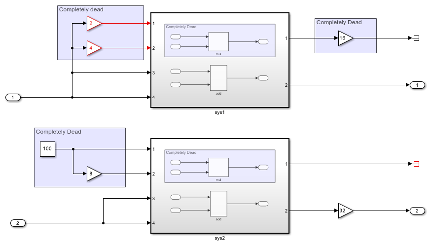
The mul block is unused in both sys1 and sys2 subsystems and is eliminated from the generated code. Inputs to the mul block are completely unconnected as well and are eliminated from the generated code.
Partially connected: For modules generated from identical atomic subsystems, model blocks, or ForEach subsystem blocks that are reused across multiple instances, the internal module logic and logic for blocks connected to the module are classified as partially connected even if one instance of the module uses the repeated logic. For example, open the model atomic_partial_connected.slx.
open_system('atomic_partial_connected')

The mul block is used in sys2, classifying the block as partially connected and the block logic is retained in the generated code. The inputs to the mul block are completely unused and eliminated from the generated code.
Limitations
1. When your model contains multiple instances of atomic subsystems, model references, or ForEach subsystem blocks, if these blocks are determined to be partially connected during HDL code generation, then all ports are preserved in the generated code.
2. For models that have vector signals, Demux blocks act as boundaries for the redundant logic optimization. Redundant logic and components that are downstream of the Demux block are removed during HDL code generation. The optimization does not cross the Demux block boundary and therefore preserves components that are upstream of the Demux block. This limitation when using vectors also applies when you convert buses to vectors.
Open the model hdlcoder_vector_redundant_logic.
open_system('hdlcoder_vector_redundant_logic')
sim('hdlcoder_vector_redundant_logic');

The DUT subsystem contains an innerSubsystem block. This subsystem has one active output port and the other port is terminated.
open_system('hdlcoder_vector_redundant_logic/DUT')

To generate HDL code for the DUT subsystem, run this command:
makehdl('hdlcoder_vector_redundant_logic/DUT')
The generated HDL code shows that the Add block performs a vector Add calculation. Both the Gain block and Add block are preserved in the generated HDL code as the redundant logic optimization does not cross the Demux block boundary.
ENTITY DUT IS
 PORT( In1       :   IN    std_logic_vector(7 DOWNTO 0);  -- int8
       Out1      :   OUT   std_logic_vector(8 DOWNTO 0);  -- sfix9
       Out2      :   OUT   std_logic_vector(8 DOWNTO 0)  -- sfix9
       );
END DUT;
ARCHITECTURE rtl OF DUT IS
-- Component Declarations
COMPONENT innerSubsystem
  PORT( In1      :   IN    vector_of_std_logic_vector9(0 TO 1);  -- sfix9 [2]
        Out1     :   OUT   std_logic_vector(8 DOWNTO 0)  -- sfix9
        );
END COMPONENT;
...
In1_signed <= signed(In1);
Gain1_cast <= resize(In1_signed & '0' & '0', 16);
Gain1_out1 <= Gain1_cast(7 DOWNTO 0);
Mux_out1(0) <= signed(In1);
Mux_out1(1) <= Gain1_out1;
Add_out1_gen: FOR t_0 IN 0 TO 1 GENERATE
  Add_out1(t_0) <= resize(Mux_out1(t_0), 9) + resize(Mux_out1(t_0), 9);
END GENERATE Add_out1_gen;
outputgen: FOR k IN 0 TO 1 GENERATE
  Add_out1_1(k) <= std_logic_vector(Add_out1(k));
END GENERATE;
Out2 <= std_logic_vector(Add_out1(0));
...
END rtl;