Gate Valve (IL)
Gate valve in an isothermal liquid system

Libraries:
Simscape /
Fluids /
Isothermal Liquid /
Valves & Orifices /
Flow Control Valves
Description
The Gate Valve (IL) block represents flow control by a gate valve in an isothermal liquid network. The valve comprises a round, sharp-edged orifice and a round gate with the same diameter. The gate opens or closes according to the displacement signal at port S. A positive signal retracts the gate and opens the valve.
Opening Area
Gate Valve Opening Schematic
The area open to flow as the gate retracts is:
where d0 is the Valve orifice diameter. The area shielded by the gate in a partially open valve is:
where Δl is the gate displacement, which is the sum of the signal at port S and the Gate position when fully covering orifice.
If displacement exceeds the Orifice diameter, the valve area Aopen is the sum of the maximum orifice area and the Leakage area:
For any combination of the signal at port S and the gate offset that is less than 0, the minimum valve area is the Leakage area.
Numerically Smoothed Displacement
When the valve is in a near-open or near-closed position,
you can maintain numerical robustness in your simulation by adjusting the
Smoothing factor parameter. If the Smoothing
factor parameter is nonzero, the block smoothly saturates the gate
displacement between 0 and the Valve orifice
diameter parameter. For more information, see Numerical Smoothing.
Mass Flow Rate Equation
Mass is conserved through the valve:
The mass flow rate through the valve is calculated as:
where:
Cd is the Discharge coefficient.
Avalve is the valve open area.
Aport is the Cross-sectional area at ports A and B.
is the average fluid density.
Δp is the valve pressure difference pA – pB.
The critical pressure difference, Δpcrit, is the pressure differential associated with the Critical Reynolds number, Recrit, which is the flow regime transition point between laminar and turbulent flow:
Pressure loss describes the reduction of pressure in the valve due to a decrease in area. PRloss is calculated as:
Pressure recovery describes the positive pressure change in the valve due to an increase in area. If you do not want to capture this increase in pressure, clear the Pressure recovery check box. In this case, PRloss is 1.
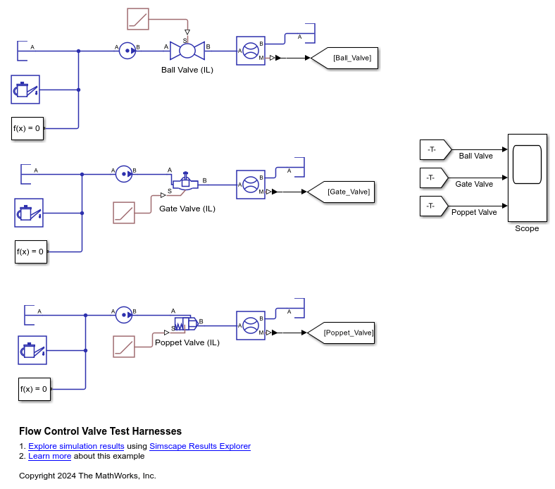
Examples
This example uses test harnesses to compare the Ball Valve (IL), Gate Valve (IL), and Poppet Valve (IL) blocks. A test harness is a minimum viable model that you can use to parameterize blocks or isolate dynamics.
Model
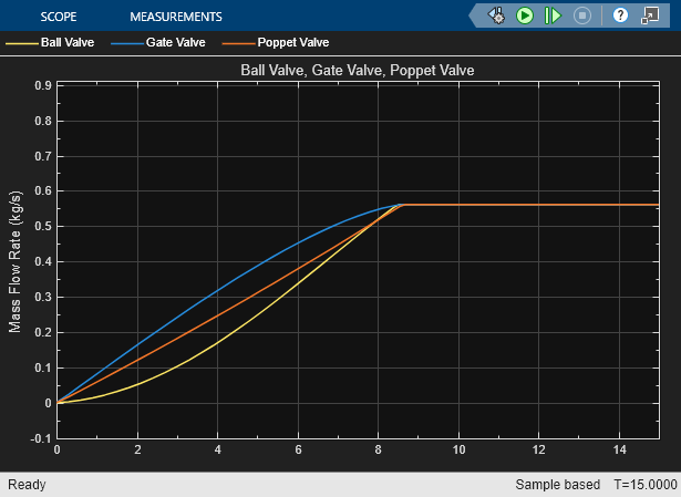
Simulation Results from Scopes
This figure shows the mass flow rate through each of the valves. All three valves start closed and slowly open before reaching their maximum area. At the maximum area, the mass flow rate also reaches its maximum and cannot increase further. Each curve has a different profile while opening because each valve has a different area profile that depends on the valve geometry.
Ports
Input
Conserving
Parameters
Extended Capabilities
Version History
Introduced in R2020a