Main Content

Heat Exchanger (TL-MA)

Models heat exchange between a moist air network and a thermal liquid network

Since R2020b

Libraries:
Simscape / Fluids / Heat Exchangers / Thermal Liquid - Moist Air

Description

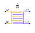
The Heat Exchanger (TL-MA) block models a heat exchanger with one moist air network, which flows between ports A2 and B2, and one thermal liquid network, which flows between ports A1 and B1. The fluid streams can be aligned in parallel, counter, or cross-flow configurations.

A thermal liquid-moist air heat exchanger is not appropriate for refrigeration cooling systems. See Condenser Evaporator (2P-MA) or Condenser Evaporator (TL-2P) for heat exchangers that can be employed in refrigeration applications.

You can model the moist air side as flow within tubes, flow around thermal liquid tubing, or by an empirical, generic parameterization. The moist air side comprises air, trace gas, and water vapor that may condense throughout the heat exchange cycle. The block model accounts for the latent heat that is released when water condenses on the heat transfer surface. This liquid layer does not collect on the surface and is assumed to be completely removed from the downstream moist air flow. The moisture condensation rate is returned as a physical signal at port W.

The block uses the Effectiveness-NTU (E-NTU) method to model heat transfer through the shared wall. Fouling on the exchanger walls, which increases thermal resistance and reduces the heat exchange between the two fluids, is also modeled. You can also optionally model fins on both the moist air and thermal liquid sides. Pressure loss due to viscous friction on both sides of the exchanger can be modeled analytically or by generic parameterization, which you can use to tune to your own data.

You can model the thermal liquid side as flow within tubes, flow around moist air tubing, or by an empirical, generic parameterization.

Heat Exchanger Configuration

The heat exchanger effectiveness is based on the selected heat exchanger configuration, the fluid properties, the tube geometry and flow configuration on each side of the exchanger, and the usage and size of fins.

Flow Arrangement

The Flow arrangement parameter assigns the relative flow paths between the two sides:

  • Parallel flow indicates the fluids are moving in the same direction.

  • Counter flow indicates the fluids are moving in parallel, but opposite directions.

  • Cross flow indicates the fluids are moving perpendicular to each other.

Thermal Mixing

When Flow arrangement is set to Cross flow, use the Cross flow arrangement parameter to indicate whether the thermal liquid or moist air flows are separated into multiple paths by baffles or walls. Without these separations, the flow can mix freely and is considered mixed. Both fluids, one fluid, or neither fluid can be mixed in the cross-flow arrangement. Mixing homogenizes the fluid temperature along the direction of flow of the second fluid, and varies perpendicular to the second fluid flow.

Unmixed flows vary in temperature both along and perpendicular to the flow path of the second fluid.

Sample Cross-Flow Configurations

Note that the flow direction during simulation does not impact the selected flow arrangement setting. The ports on the block do not reflect the physical positions of the ports in the physical heat exchange system.

All flow arrangements are single-pass, which means that the fluids do not make multiple turns in the exchanger for additional points of heat transfer. To model a multi-pass heat exchanger, you can arrange multiple Heat Exchanger (TL-MA) blocks in series or in parallel.

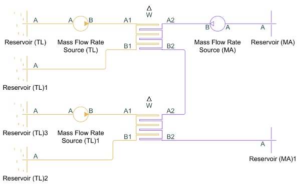
For example, to achieve a two-pass configuration on the moist air side and a single-pass configuration on the thermal liquid side, you can connect the moist air sides in series and the thermal liquid sides to the same input in parallel (such as two Mass Flow Rate Source blocks with half of the total mass flow rate), as shown below.

Flow Geometry

The Flow geometry parameter sets the flow arrangement of the fluid of the respective dialog tab as either inside a tube or set of tubes, or perpendicular to a tube bank. You can also specify an empirical, generic configuration.

When Flow geometry is set to Flow perpendicular to bank of circular tubes, use the Tube bank grid arrangement parameter to define the tube bank alignment of the other fluid as either Inline or Staggered. The red, downward-pointing arrow in the figure below indicates the direction of the fluid flowing external to the tube bank. The Inline figure also shows the Number of tube rows along flow direction and the Number of tube segments in each tube row parameters. Here, flow direction refers to the fluid of the respective dialog tab, and tube refers to the tubing of the other fluid. The Length of each tube segment in a tube row parameter is indicated in the Staggered figure.

Only one fluid can have Flow geometry set to Flow perpendicular to bank of circular tubes at a time. The other fluid must be configured to either Flow inside one or more tubes or Generic. If Flow geometry for both fluids is set to Flow perpendicular to bank of circular tubes, you will receive an error.

Fins

The heat exchanger configuration does not have fins when the Total fin surface area parameter is 0 m^2. Fins introduce additional surface area for heat transfer. Each fluid side has a separate fin area and parameters that describe the fins in that fluid. For example, when the thermal liquid flows inside the tubes and the moist air flows outside of the tubes, the Total fin surface area and Fin efficiency parameters in the Thermal Liquid 1 section describe the fins protruding into the tube. The Total fin surface area and Fin efficiency parameters in the Moist Air 2 section describe the fins outside of the tubes.

Effectiveness-NTU Heat Transfer

The heat transfer rate is calculated over the averaged properties of both fluids.

The heat transfer is calculated as:

Q=ϵCMin(TIn,TLTIn,MA),

where:

  • CMin is the lesser of the heat capacity rates of the two fluids. The heat capacity rate is the product of the fluid specific heat, cp, and the fluid mass flow rate. CMin is always positive.

  • TIn,TL is the inlet temperature of the thermal liquid.

  • TIn,MA is the inlet temperature of the moist air.

  • ε is the heat exchanger effectiveness.

Effectiveness is a function of the heat capacity rate and the number of transfer units, NTU, and also varies based on the heat exchanger flow arrangement, which is discussed in more detail in Effectiveness by Flow Arrangement. The NTU is calculated as:

NTU=1CMinR,

where R is the total thermal resistance between the two flows, due to convection, conduction, and any fouling on the tube walls:

R=1UTLATh,TL+FTLATh,TL+RW+FMAATh,MA+1UMAATh,MA,

and where:

  • U is the convective heat transfer coefficient of the respective fluid. This coefficient is discussed in more detail in Heat Transfer Coefficients.

  • F is the Fouling factor on the thermal liquid or moist air side, respectively.

  • RW is the Thermal resistance through heat transfer surface.

  • ATh is the heat transfer surface area of the respective side of the exchanger. ATh is the sum of the wall surface area, AW, and the Total fin surface area, AF:

    ATh=AW+ηFAF,

    where ηF is the Fin efficiency.

Effectiveness by Flow Arrangement

The heat exchanger effectiveness varies according to its flow configuration and the mixing in each fluid.

  • When Flow arrangement is set to Parallel flow:

    ϵ=1exp[NTU(1+CR)]1+CR

  • When Flow arrangement is set to Counter flow:

    ϵ=1exp[NTU(1CR)]1CRexp[NTU(1CR)]

  • When Flow arrangement is set to Cross flow and Cross flow arrangement is set to Both fluids unmixed:

    ϵ=1exp{NTU0.22CR[exp(CRNTU0.78)1]}

  • When Flow arrangement is set to Cross flow and Cross flow arrangement is set to Both fluids mixed:

    ϵ=[11exp(NTU)+CR1exp(CRNTU)1NTU]1

When one fluid is mixed and the other unmixed, the equation for effectiveness depends on the relative heat capacity rates of the fluids. When Flow arrangement is set to Cross flow and Cross flow arrangement is set to either Thermal Liquid 1 mixed & Moist Air 2 unmixed or Thermal Liquid 1 unmixed & Moist Air 2 mixed:

  • When the fluid with Cmax is mixed and the fluid with Cmin is unmixed:

    ϵ=1CR(1exp{CR{1exp(NTU)}})

  • When the fluid with Cmin is mixed and the fluid with Cmax is unmixed:

    ϵ=1exp{1CR[1exp(CRNTU)]}

CR denotes the ratio between the heat capacity rates of the two fluids:

CR=CMinCMax.

Condensation

On the moist air side, a layer of condensation may form on the heat transfer surface. This liquid layer can influence the amount of heat transferred between the moist air and thermal liquid. The equations for E-NTU heat transfer above are given for dry heat transfer. To correct for the influence of condensation, the E-NTU equations are additionally calculated with the wet parameters listed below. Whichever of the two calculated heat flow rates results in a larger amount of moist air side cooling is used in heat calculations for each zone [1]. To use this method, the Lewis number is assumed to be close to 1 [1], which is true for moist air.

E-NTU Quantities Used for Heat Transfer Rate Calculations

 Dry calculationWet calculation
Moist air zone inlet temperatureTin,MATin,wb,MA
Heat capacity ratem˙¯MAc¯p,MAm˙¯MAc¯eq,MA
Heat transfer coefficientUMAUMAc¯eq,MAc¯p,MA

where:

  • Tin,MA is the moist air inlet temperature.

  • Tin,wb,MA is the moist air wet-bulb temperature associated with Tin,MA.

  • m˙¯MA is the dry air mass flow rate.

  • c¯p,MA is the moist air heat capacity per unit mass of dry air.

  • c¯eq,MA is the equivalent heat capacity. The equivalent heat capacity is the change in the moist air specific enthalpy (per unit of dry air), h¯MA, with respect to temperature at saturated moist air conditions:

    c¯eq,MA=(h¯MATMA)s.

The mass flow rate of the condensed water vapor leaving the moist air mass flow depends on the relative humidity between the moist air inlet and the channel wall and the heat exchanger NTUs:

m˙cond=m˙¯MA(Wwall,MAWin,MA)(1eNTUMA),

where:

  • Wwall,MA is the humidity ratio at the heat transfer surface.

  • Win,MA is the humidity ratio at the moist air flow inlet.

  • NTUMA is the number of transfer units on the moist air side, calculated as:

    NTUMA=UMAc¯eq,MAc¯p,MAATh,MAm˙¯MAc¯eq,MA.

The energy flow associated with water vapor condensation is based on the difference between the vapor specific enthalpy, hwater, wall, and the specific enthalpy of vaporization, hfg, for water:

ϕCond=m˙cond(hwater,wallhfg).

The condensate is assumed to not accumulate on the heat transfer surface, and does not influence geometric parameters such as tube diameter.

Heat Transfer Coefficients

The equations below apply to both the thermal liquid and moist air sides and use the respective fluid properties.

Flow Inside Tubes

The convective heat transfer coefficient varies according to the fluid Nusselt number:

U=NukDH,

where:

  • Nu is the mean Nusselt number, which depends on the flow regime.

  • k is the fluid thermal conductivity.

  • DH is tube hydraulic diameter.

For turbulent flows, the Nusselt number is calculated with the Gnielinski correlation:

Nu=fD8(Re1000)Pr1+12.7f8(Pr2/31),

where:

  • Re is the fluid Reynolds number.

  • Pr is the fluid Prandtl number.

For laminar flows, the Nusselt number is set by the Laminar flow Nusselt number parameter.

For transitional flows, the Nusselt number is a blend between the laminar and turbulent Nusselt numbers.

Flow Across a Tube Bank

When Flow geometry is set to Flow perpendicular to bank of circular tubes, the Nusselt number is calculated based on the Hagen number, Hg, and depends on the Tube bank grid arrangement setting:

Nu={0.404Lq1/3(Re+1Re+1000)0.1,Inline0.404Lq1/3,Staggered

where:

Lq={1.18Pr(4lT/πDlL)Hg(Re),Inline0.92Pr(4lT/πDlD)Hg(Re),Staggered with lLD0.92Pr(4lTlL/πD2lLlD)Hg(Re),Staggered with lL<D

  • D is the Tube outer diameter.

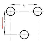
  • lL is the Longitudinal tube pitch (along flow direction), the distance between the tube centers along the flow direction. Flow direction is the direction of flow of the external fluid.

  • lT is the Transverse tube pitch (perpendicular to flow direction), the distance between the centers of the tubing in one row of the other fluid.

  • lD is the diagonal tube spacing, calculated as lD=(lT2)2+lL2.

For more information on calculating the Hagen number, see [6].

The measurements lL and lT are shown in the tube bank cross-section below. These distances are the same for both grid bank arrangement types.

Cross-section of Tubing with Pitch Measurements

Empirical Nusselt Number Formulation

When the Heat transfer coefficient model parameter is set to Colburn equation or when Flow geometry is set to Generic, the Nusselt number is calculated by the empirical the Colburn equation:

Nu=aRebPrc,

where a, b, and c are defined in the Coefficients [a, b, c] for a*Re^b*Pr^c parameter.

Pressure Loss

The equations below apply to both the thermal liquid and moist air sides and use the respective fluid properties.

Flows Inside Tubes

The pressure loss due to viscous friction varies depending on flow regime and configuration.

For turbulent flows, when the Reynolds number is above the Turbulent flow lower Reynolds number limit parameter, and when Pressure loss model is set to Correlations for flow inside tubes, the pressure loss due to friction is calculated in terms of the Darcy friction factor.

For the thermal liquid side, the pressure differential between a port A1 and the internal node I1 is:

pA1pI1=fD,Am˙A1|m˙A1|2ρDHACS2(L+LAdd2),

where:

  • m˙A1 is the total flow rate through port A1.

  • fD,A is the Darcy friction factor, according to the Haaland correlation. When the Local resistance specification parameter is Aggregate equivalent length,

    fD,A1={1.8log10[6.9ReA1+(ϵR3.7DH)1.11]}-2,

    where εR is the thermal liquid pipe Internal surface absolute roughness. The friction factor is dependent on the Reynolds number, and the block calculates this value at both ports for each liquid.

  • L is the Total length of each tube on the thermal liquid side.

  • LAdd is the thermal liquid side Aggregate equivalent length of local resistances, which is the equivalent length of a tube that introduces the same amount of loss as the sum of the losses due to other local resistances in the tube.

  • ACS is the total tube cross-sectional area.

The pressure differential between port B1 and internal node I1 is:

pB1pI1=fD,Bm˙B1|m˙B1|2ρDHACS2(L+LAdd2),

where m˙B1 is the total flow rate through port B1.

When the Local resistance specification parameter is Aggregate equivalent length, the Darcy friction factor at port B1 is:

fD,B1={1.8log10[6.9ReB1+(ϵR3.7DH)1.11]}-2.

When the Local resistance specification parameter is Local loss coefficient, the Darcy friction factors at ports A1 and B1 are

fD,A1={1.8log10[6.9ReA1+(ϵR3.7DH)1.11]}-2+Clocalloss(DHL)fD,B1={1.8log10[6.9ReB1+(ϵR3.7DH)1.11]}-2+Clocalloss(DHL)

where Clocalloss is the value of the Total local loss coefficient parameter.

For laminar flows, when the Reynolds number is below the Laminar flow upper Reynolds number limit parameter, and when Pressure loss model is set to Correlations for flow inside tubes, the block calculates the pressure loss due to friction in terms of the Laminar friction constant for Darcy friction factor parameter, λ. λ is a user-defined parameter when Tube cross-section is Generic. Otherwise, the block calculates the value internally.

The pressure differential between port A1 and internal node I1 is:

pA1pI1=λμm˙A12ρDH2ACS(L+LAdd2),

where μ is the fluid dynamic viscosity. The pressure differential between port B1 and internal node I1 is:

pB1pI1=λμm˙B12ρDH2ACS(L+LAdd2).

For transitional flows, when Pressure loss model is set to Correlations for flow inside tubes, the pressure differential due to viscous friction is a smoothed blend between the values for laminar and turbulent pressure losses.

Empirical Formulation for Flows Inside Tubes

When Pressure loss model is set to Pressure loss coefficient or when Flow geometry is set to Generic, the pressure losses due to viscous friction are calculated with an empirical pressure loss coefficient, ξ. The same equations apply to both the moist air and thermal liquid sides and use the respective fluid properties.

For the thermal liquid side, the pressure differential between port A1 and internal node I1 is:

pA1pI1=12ξm˙A1|m˙A1|2ρACS2.

The pressure differential between port B1 and internal node I1 is:

pB1pI1=12ξm˙B1|m˙B1|2ρACS2.

Pressure Loss for Flow Across Tube Banks

When Flow geometry is set to Flow perpendicular to bank of circular tubes, the Hagen number is used to calculate the pressure loss due to viscous friction. The same equations apply to both the moist air and thermal liquid sides and use the respective fluid properties.

For the moist air side, the pressure differential between port A2 and internal node I2 is:

pA2pI2=12μ2NRρD2Hg(Re),

where:

  • μ is the moist air fluid dynamic viscosity.

  • NR is the Number of tube rows along flow direction. When moist air is flowing external to a tube bank, this is the number of thermal liquid tube rows along the direction of the moist air flow.

The pressure differential between port B2 and internal node I2 is:

pB2pI2=12μ2NRρD2Hg(Re).

Empirical Formulation for Flows Across Tubes

When the Pressure loss model is set to Euler number per tube row or when Flow geometry is set to Generic, the pressure loss due to viscous friction is calculated with a pressure loss coefficient, in terms of the Euler number, Eu:

Eu=ξNR,

where ξ is the empirical pressure loss coefficient.

The pressure differential between port A2 and internal node I2 is:

pA2pI2=12NREum˙A2|m˙A2|2ρACS2.

The pressure differential between port B2 and internal node I2 is:

pB2pI2=12NREum˙B2|m˙B2|2ρACS2.

Conservation Equations

Thermal Liquid

The total mass accumulation rate in the thermal liquid is defined as:

dMTLdt=m˙A1+m˙B1,

where:

  • MTL is the total mass of the thermal liquid.

  • m˙A1 is the mass flow rate of the fluid at port A1.

  • m˙B1 is the mass flow rate of the fluid at port B1.

The flow is positive when flowing into the block through the port.

The energy conservation equation relates the change in specific internal energy to the heat transfer by the fluid:

MTLduTLdt+uTL(m˙A1+m˙B1)=ϕA1+ϕB1Q,

where:

  • uTL is the thermal liquid specific internal energy.

  • φA1 is the energy flow rate at port A1.

  • φB1 is the energy flow rate at port B1.

  • Q is heat transfer rate, which is positive when leaving the thermal liquid volume.

Moist Air

There are three equations for mass conservation on the moist air side: one for the moist air mixture, one for condensed water vapor, and one for the trace gas.

Note

If Trace gas model is set to None in the Moist Air Properties (MA) block, the trace gas is not modeled in blocks in the moist air network. In the Heat Exchanger (TL-MA) block, this means that the conservation equation for trace gas is set to 0.

The moist air mixture mass accumulation rate accounts for the changes of the entire moist air mass flow through the exchanger ports and the condensation mass flow rate:

dMMAdt=m˙A2+m˙B2m˙Cond.

The mass conservation equation for water vapor accounts for the water vapor transit through the moist air side and condensation formation:

dxwdtMMA+xw(m˙A2+m˙B2m˙Cond)=m˙w,A2+m˙w,B2m˙Cond,

where:

  • xw is the mass fraction of the vapor. dxwdt is the rate of change of this fraction.

  • m˙w,A2 is the water vapor mass flow rate at port A2.

  • m˙w,B2 is the water vapor mass flow rate at port B2.

  • m˙Cond is the rate of condensation.

The trace gas mass balance is:

dxgdtMMA+xg(m˙A2+m˙B2m˙Cond)=m˙g,A2+m˙g,B2,

where:

  • xg is the mass fraction of the trace gas. dxgdt is the rate of change of this fraction.

  • m˙g,A2 is the trace gas mass flow rate at port A2.

  • m˙g,B2 is the trace gas mass flow rate at port B2.

Energy conservation on the moist air side accounts for the change in specific internal energy due to heat transfer and water vapor condensing out of the moist air mass:

MMAduMAdt+uMA(m˙A2+m˙B2m˙Cond)=ϕA2+ϕB2+QϕCond,

where:

  • ϕA2 is the energy flow rate at port A2.

  • ϕB2 is the energy flow rate at port B2.

  • ϕCond is the energy flow rate due to condensation.

The heat transferred to or from the moist air, Q, is equal to the heat transferred from or to the thermal liquid.

Ports

Conserving

expand all

Inlet or outlet port associated with the thermal liquid.

Inlet or outlet port associated with the thermal liquid.

Inlet or outlet port associated with the moist air.

Inlet or outlet port associated with the moist air.

Output

expand all

Water condensation rate in the moist air flow. The condensate does not accumulate on the heat transfer surface.

Parameters

expand all

Configuration

Flow path alignment between heat exchanger sides. The available flow arrangements are:

  • Parallel flow. The flows run in the same direction.

  • Counter flow. The flows run parallel to each other, in the opposite directions.

  • Cross flow. The flows run perpendicular to each other.

Select whether each of the fluids can mix in its channel. Mixed flow means that the fluid is free to move in the transverse direction as it travels along the flow path. Unmixed flow means that the fluid is restricted to travel only along the flow path. For example, a side with fins is considered an unmixed flow.

Dependencies

To enable this parameter, set Flow arrangement to Cross flow.

Thermal resistance of the wall separating the two sides of the heat exchanger. The wall thermal resistance, wall fouling, and the fluid convective heat transfer coefficient influence the amount of heat transferred between the flows.

Flow area at the thermal liquid port A1.

Flow area at the thermal liquid port B1.

Flow area at the moist air port A2.

Flow area at the moist air port B2.

Thermal Liquid 1

Thermal liquid flow path. The flow can run externally over a set of tubes or internal to a tube or set of tubes. You can also specify a generic parameterization based on empirical values.

Number of thermal liquid tubes. More tubes result in higher pressure losses due to viscous friction, but a larger amount of surface area for heat transfer.

Dependencies

To enable this parameter, set Flow geometry to Flow inside one or more tubes.

Total length of each thermal liquid tube.

Dependencies

To enable this parameter, set Flow geometry to Flow inside one or more tubes.

Cross-sectional shape of one tube. Set to Generic to specify an arbitrary cross-sectional geometry.

Dependencies

To enable this parameter, set Flow geometry to Flow inside one or more tubes.

Internal diameter of the cross-section of one tube. The cross-section and diameter are uniform along the tube. The size of the diameter influences the pressure loss and heat transfer calculations.

Dependencies

To enable this parameter, set Flow geometry to Flow inside one or more tubes and Tube cross-section to Circular.

Internal width of the cross-section of one tube. The cross-section and width are uniform along the tube. The width and height influence the pressure loss and heat transfer calculations.

Dependencies

To enable this parameter, set Flow geometry to Flow inside one or more tubes and Tube cross-section to Rectangular.

Internal height of one tube cross-section. The cross-section and height are uniform along the tube. The width and height influence the pressure loss and heat transfer calculations.

Dependencies

To enable this parameter, set Flow geometry parameterization of Flow inside one or more tubes and Tube cross-section to Rectangular.

Smaller diameter of the annular cross-section of one tube. The cross-section and inner diameter are uniform along the tube. The inner diameter influences the pressure loss and heat transfer calculations. Heat transfer occurs through the inner surface of the annulus.

Dependencies

To enable this parameter, set Flow geometry parameterization of Flow inside one or more tubes and Tube cross-section to Annular.

Larger diameter of the annular cross-section of one tube. The cross-section and outer diameter are uniform along the tube. The outer diameter influences the pressure loss and heat transfer calculations.

Dependencies

To enable this parameter, set Flow geometry to Flow inside one or more tubes and Tube cross-section to Annular.

Internal flow area of each tube.

Dependencies

To enable this parameter, set Flow geometry to Flow inside one or more tubes and Tube cross-section to Generic.

Perimeter of the tube cross-section that the fluid touches. The cross-section and perimeter are uniform along the tube. This value is applied in pressure loss calculations.

Dependencies

To enable this parameter, set Flow geometry to Flow inside one or more tubes and Tube cross-section to Generic.

Tube perimeter for heat transfer calculations. This is often the same as the tube perimeter, but in cases such as the annular cross-section, this may be only the inner or outer diameter, depending on the heat-transferring surface. The cross-section and tube perimeter are uniform along the tube.

Dependencies

To enable this parameter, set Flow geometry to Flow inside one or more tubes and Tube cross-section to Generic.

Method of pressure loss calculation due to viscous friction. Different models are available for different flow configurations. The settings are:

  • Correlation for flow inside tubes. Use this setting to calculate the pressure loss with the Haaland correlation.

  • Pressure loss coefficient. Use this setting to calculate the pressure loss based on an empirical loss coefficient.

  • Euler number per tube row. Use this setting to calculate the pressure loss based on an empirical Euler number.

  • Correlation for flow over tube bank. Use this setting to calculate the pressure loss based on the Hagen number.

The pressure loss models available depend on the Flow geometry setting.

Dependencies

When Flow geometry is set to Flow inside one or more tubes, Pressure loss model can be set to either:

  • Pressure loss coefficient.

  • Correlation for flow inside tubes.

When Flow geometry is set to Flow perpendicular to bank of circular tubes, Pressure loss model can be set to either:

  • Correlation for flow over tube bank.

  • Euler number per tube row.

When Flow geometry is set to Generic, the Pressure loss model parameter is disabled. Pressure loss is calculated empirically with the Pressure loss coefficient, delta_p/(0.5*rho*v^2) parameter.

Empirical loss coefficient for all pressure losses in the channel. This value accounts for wall friction and minor losses due to bends, elbows, and other geometry changes in the channel.

The loss coefficient can be calculated from a nominal operating condition or be tuned to fit experimental data. It is defined as:

ξ=Δp12ρv2,

where Δp is the pressure drop, ρ is the thermal liquid density, and v is the flow velocity.

Dependencies

To enable this parameter, set either:

  • Flow geometry to Flow inside one or more tubes and Pressure loss model to Pressure loss coefficient.

  • Flow geometry to Generic.

Method for quantifying pressure losses in the Haaland correlation.

Dependencies

To enable this parameter, set Flow geometry to Flow inside one or more tubes and Pressure loss model to Correlation for flow inside tubes.

Combined length of all local resistances per tube. This value is the length of tubing that results in the same pressure losses as the sum of all minor losses in the tube due to resistances such as bends, tees, or unions. A longer combined length results in larger pressure losses. The block adds the value of this parameter to the Total length of each tube parameter in the calculations of pressure loss due to friction.

Dependencies

To enable this parameter, set Flow geometry to Flow inside one or more tubes, Pressure loss model to Correlations for flow inside tubes, and Local resistance specification to Aggregate equivalent length.

Local pressure loss coefficient over the system. You can use this parameter to calibrate your system to match experimental results.

Dependencies

To enable this parameter, set Flow geometry to Flow inside one or more tubes, Pressure loss model to Correlation for flow inside tubes, and Local resistance specification to Local loss coefficient.

Mean height of tube surface defects. A rougher wall results in larger pressure losses in the turbulent regime for pressure loss calculated with the Haaland correlation.

Dependencies

To enable this parameter, set Flow geometry to Flow inside one or more tubes and either:

  • Pressure loss model

  • Heat transfer coefficient model

to Correlation for flow inside tubes.

Largest Reynolds number that indicates laminar flow. Between this value and the Turbulent flow lower Reynolds number limit, the flow regime is transitional.

Dependencies

To enable this parameter, set Flow geometry to Flow inside one or more tubes and either:

  • Pressure loss model

  • Heat transfer model

to Correlation for flow inside tubes.

Smallest Reynolds number that indicates turbulent flow. Between this value and the Laminar flow upper Reynolds number limit, the flow regime is transitional between the laminar and turbulent regimes.

Dependencies

To enable this parameter, set Flow geometry to Flow inside one or more tubes and Pressure loss model to Correlation for flow inside tubes.

Coefficient in pressure loss equations for viscous friction in laminar flows. This parameter is also known as the shape factor. The default value corresponds to a circular tube cross-section.

Dependencies

To enable this parameter, set Flow geometry to Correlation for flow inside tubes, Tube cross section to Generic, and Pressure loss model to Correlation for flow inside tubes.

Method of calculating the heat transfer coefficient between the fluid and the wall. The available settings are:

  • Colburn equation. Use this setting to calculate the heat transfer coefficient with user-defined variables a, b, and c of the Colburn equation.

  • Correlation for flow over tube bank. Use this setting to calculate the heat transfer coefficient based on the tube bank correlation using the Hagen number.

  • Correlation for flow inside tubes. Use this setting to calculate the heat transfer coefficient for pipe flows with the Gnielinski correlation.

Dependencies

To enable this parameter, set Flow geometry to either:

  • Flow perpendicular to bank of circular tubes.

  • Flow inside one or more tubes.

Three-element vector containing the empirical coefficients of the Colburn equation. The Colburn equation is a formulation for calculating the Nusselt Number. The general form of the Colburn equation is:

Nu=aRebPrc.

When the Heat transfer coefficient model is set to Colburn equation and Flow geometry is set to Flow inside one or more tubes, or Flow geometry is set to Generic, the default Colburn equation is:

Nu=0.023Re0.8Pr1/3.

When the Heat transfer coefficient model is set to Colburn equation and Flow geometry is set to Flow perpendicular to bank of circular tubes, the default Colburn equation is:

Nu=0.27Re0.63Pr0.36.

Dependencies

To enable this parameter, set:

  1. Flow geometry to either:

    • Flow inside one or more tubes

    • Flow perpendicular to bank of circular tubes

    and Heat transfer coefficient model to Colburn equation.

  2. Flow geometry to Generic.

Ratio of convective to conductive heat transfer in the laminar flow regime. The fluid Nusselt number influences the heat transfer rate and depends on the tube cross-section.

Dependencies

To enable this parameter, set Flow geometry to Flow inside one or more tubes, Tube cross-section to Generic, and Heat transfer parameterization to Correlation for flow inside tubes.

Alignment of tubes in a tube bank. Rows are either in line with their neighbors, or staggered.

  • Inline: All tube rows are located directly behind each other.

  • Staggered: Tubes of the one tube row are located at the gap between tubes of the previous tube row.

Tube alignment influences the Nusselt number and the heat transfer rate.

Dependencies

To enable this parameter, set Flow geometry to Flow perpendicular to bank of circular tubes.

Number of moist air tube rows in a tube bank. The rows are aligned with the direction of thermal liquid flow.

Dependencies

To enable this parameter, set Flow geometryto Flow perpendicular to bank of circular tubes.

Number of moist air tubes in each row of a tube bank. This measurement is perpendicular to the thermal liquid flow.

Dependencies

To enable this parameter, set Flow geometry to Flow perpendicular to bank of circular tubes.

Length of each moist air tube that spans a tube row. All tubes in a tube bank are the same length.

Dependencies

To enable this parameter, set Flow geometry to Flow perpendicular to bank of circular tubes.

Outer diameter of a moist air tube. The cross-section is uniform along a tube and so the diameter is constant throughout. This value influences the losses in the flow across a tube bank due to viscous friction.

Dependencies

To enable this parameter, set Flow geometry to Flow perpendicular to bank of circular tubes.

Distance between tube centers of the moist air tube bank aligned with the direction of flow of the thermal liquid.

Dependencies

To enable this parameter, set Flow geometry to Flow perpendicular to bank of circular tubes.

Distance between the tube centers in a row of moist air tubes. This measurement is perpendicular to the thermal liquid flow direction. See Heat Transfer Coefficients for more information.

Dependencies

To enable this parameter, set Flow geometry to Flow perpendicular to bank of circular tubes.

Empirical coefficient for pressure drop across one tube row. The Euler number is the ratio between pressure drop and fluid momentum:

Eu=ΔpN12ρv2,

where N is the Number of tube rows along flow direction, Δp is the pressure drop, ρ is the thermal liquid density, and v is the flow velocity.

Each tube row is located in a plane perpendicular to the thermal liquid flow.

Dependencies

To enable this parameter, set either:

  • Flow geometry to Flow perpendicular to bank of circular tubes and Pressure loss model to Euler number per tube row.

  • Flow geometry to Generic.

Smallest total flow area between inlet and outlet. If the channel is a collection of ducts, tubes, slots, or grooves, the minimum free-flow area is the sum of the smallest areas.

Dependencies

To enable this parameter, set Flow geometry to Generic.

Total area of the heat transfer surface, excluding fins.

Dependencies

To enable this parameter, set Flow geometry to Generic.

Total volume of thermal liquid in the heat exchanger.

Dependencies

To enable this parameter, set Flow geometry to Generic.

Additional thermal resistance due to fouling layers on the surfaces of the wall. In real systems, fouling deposits grow over time. However, the growth is slow enough to be assumed constant during the simulation.

Total heat transfer surface area of both sides of all fins touching the thermal liquid. For example, if the fin is rectangular, the surface area is double the area of the rectangle.

The total heat transfer surface area is the sum of the channel surface area and the effective fin surface area, which is the product of the Fin efficiency and the Total fin surface area.

Ratio of actual heat transfer to ideal heat transfer through the fins touching the thermal liquid if the entire fin is at the primary heat transfer surface temperature.

Thermal liquid pressure at the start of the simulation.

Temperature in the thermal liquid channel at the start of the simulation. This parameter can be a scalar or a two-element vector. A scalar value represents the mean initial temperature in the channel. A vector value represents the initial temperature at the inlet and outlet in the form [inlet, outlet]. The block calculates a linear gradient between the two ports. The inlet and the outlet ports are identified according to the initial flow direction.

Moist Air 2

Moist air flow path. The flow can run externally over a set of tubes or internal to a tube or set of tubes. You can also specify a generic parameterization based on empirical values.

Number of moist air tubes. More tubes result in higher pressure losses due to viscous friction, but a larger amount of surface area for heat transfer.

Dependencies

To enable this parameter, set Flow geometry to Flow inside one or more tubes.

Total length of each moist air tube.

Dependencies

To enable this parameter, set Flow geometry to Flow inside one or more tubes.

Cross-sectional shape of one tube. Set to Generic to specify an arbitrary cross-sectional geometry.

Dependencies

To enable this parameter, set Flow geometry to Flow inside one or more tubes.

Internal diameter of the cross-section of one tube. The cross-section and diameter are uniform along the tube. The size of the diameter influences the pressure loss and heat transfer calculations.

Dependencies

To enable this parameter, set Flow geometry to Flow inside one or more tubes and Tube cross-section to Circular.

Internal width of the cross-section of one tube. The cross-section and width are uniform along the tube. The width and height influence the pressure loss and heat transfer calculations.

Dependencies

To enable this parameter, set Flow geometry to Flow inside one or more tubes and Tube cross-section to Rectangular.

Internal height of one tube cross-section. The cross-section and height are uniform along the tube. The width and height influence the pressure loss and heat transfer calculations.

Dependencies

To enable this parameter, set Flow geometry parameterization of Flow inside one or more tubes and Tube cross-section to Rectangular.

Smaller diameter of the annular cross-section of one tube. The cross-section and inner diameter are uniform along the tube. The inner diameter influences the pressure loss and heat transfer calculations. Heat transfer occurs through the inner surface of the annulus.

Dependencies

To enable this parameter, set Flow geometry parameterization of Flow inside one or more tubes and Tube cross-section to Annular.

Larger diameter of the annular cross-section of one tube. The cross-section and outer diameter are uniform along the tube. The outer diameter influences the pressure loss and heat transfer calculations.

Dependencies

To enable this parameter, set Flow geometry to Flow inside one or more tubes and Tube cross-section to Annular.

Internal flow area of each tube.

Dependencies

To enable this parameter, set Flow geometry to Flow inside one or more tubes and Tube cross-section to Generic.

Perimeter of the tube cross-section that the fluid touches. The cross-section and perimeter are uniform along the tube. This value is applied in pressure loss calculations.

Dependencies

To enable this parameter, set Flow geometry to Flow inside one or more tubes and Tube cross-section to Generic.

Tube perimeter for heat transfer calculations. This is often the same as the tube perimeter, but in cases such as the annular cross-section, this may be only the inner or outer diameter, depending on the heat-transferring surface. The cross-section and tube perimeter are uniform along the tube.

Dependencies

To enable this parameter, set Flow geometry to Flow inside one or more tubes and Tube cross-section to Generic.

Method of pressure loss calculation due to viscous friction. Different models are available for different flow configurations. The settings are:

  • Correlation for flow inside tubes. Use this setting to calculate the pressure loss with the Haaland correlation.

  • Pressure loss coefficient. Use this setting to calculate the pressure loss based on an empirical loss coefficient.

  • Euler number per tube row. Use this setting to calculate the pressure loss based on an empirical Euler number.

  • Correlation for flow over tube bank. Use this setting to calculate the pressure loss based on the Hagen number.

The pressure loss models available depend on the Flow geometry setting.

Dependencies

When Flow geometry is set to Flow inside one or more tubes, Pressure loss model can be set to either:

  • Pressure loss coefficient.

  • Correlation for flow inside tubes.

When Flow geometry is set to Flow perpendicular to bank of circular tubes, Pressure loss model can be set to either:

  • Correlation for flow over tube bank.

  • Euler number per tube row.

When Flow geometry is set to Generic, the Pressure loss model parameter is disabled. Pressure loss is calculated empirically with the Pressure loss coefficient, delta_p/(0.5*rho*v^2) parameter.

Empirical loss coefficient for all pressure losses in the channel. This value accounts for wall friction and minor losses due to bends, elbows, and other geometry changes in the channel.

The loss coefficient can be calculated from a nominal operating condition or be tuned to fit experimental data. The coefficient is defined as:

ξ=Δp12ρv2,

where Δp is the pressure drop, ρ is the moist air density, and v is the flow velocity.

Dependencies

To enable this parameter, set either:

  • Flow geometry to Generic.

  • Pressure loss model to Pressure loss coefficient.

Method for quantifying pressure losses in the Haaland correlation.

Dependencies

To enable this parameter, set Flow geometry to Flow inside one or more tubes and Pressure loss model to Correlation for flow inside tubes.

Combined length of all local resistances per tube. This value is the length of tubing that results in the same pressure losses as the sum of all minor losses in the tube due to resistances such as bends, tees, or unions. A longer combined length results in larger pressure losses. The block adds the value of this parameter to the Total length of each tube parameter in the calculations of pressure loss due to friction.

Dependencies

To enable this parameter, set Flow geometry to Flow inside one or more tubes, Pressure loss model to Correlations for flow inside tubes, and Local resistance specification to Aggregate equivalent length.

Local pressure loss coefficient over the system. You can use this parameter to calibrate your system to match experimental results.

Dependencies

To enable this parameter, set Flow geometry to Flow inside one or more tubes, Pressure loss model to Correlation for flow inside tubes, and Local resistance specification to Local loss coefficient.

Mean height of tube surface defects. A rougher wall results in larger pressure losses in the turbulent regime for pressure loss calculated with the Haaland correlation.

Dependencies

To enable this parameter, set Flow geometry to Flow inside one or more tubes and either:

  • Pressure loss model

  • Heat transfer coefficient model

to Correlation for flow inside tubes.

Largest Reynolds number that indicates laminar flow. Between this value and the Turbulent flow lower Reynolds number limit, the flow regime is transitional.

Dependencies

To enable this parameter, set Flow geometry to Flow inside one or more tubes and Pressure loss model to Correlation for flow inside tubes.

Smallest Reynolds number that indicates turbulent flow. Between this value and the Laminar flow upper Reynolds number limit, the flow regime is transitional between the laminar and turbulent regimes.

Dependencies

To enable this parameter, set Flow geometry to Flow inside one or more tubes and Pressure loss model to Correlation for flow inside tubes.

Coefficient in pressure loss equations for viscous friction in laminar flows. This parameter is also known as the shape factor. The default value corresponds to a circular tube cross-section.

Dependencies

To enable this parameter, set Flow geometry to Correlation for flow inside tubes, Tube cross section to Generic, and Pressure loss model to Correlation for flow inside tubes.

Method of calculating the heat transfer coefficient between the fluid and the wall. The available settings are:

  • Colburn equation. Use this setting to calculate the heat transfer coefficient with user-defined variables a, b, and c of the Colburn equation.

  • Correlation for flow over tube bank. Use this setting to calculate the heat transfer coefficient based on the tube bank correlation using the Hagen number.

  • Correlation for flow inside tubes. Use this setting to calculate the heat transfer coefficient for pipe flows with the Gnielinski correlation.

Dependencies

To enable this parameter, set Flow geometry to either:

  • Flow perpendicular to bank of circular tubes .

  • Flow inside one or more tubes.

Three-element vector containing the empirical coefficients of the Colburn equation. The Colburn equation is a formulation for calculating the Nusselt Number. The general form of the Colburn equation is:

Nu=aRebPrc.

When the Heat transfer coefficient model is set to Colburn equation and Flow geometry is set to Flow inside one or more tubes, or Flow geometry is set to Generic, the default Colburn equation is:

Nu=0.023Re0.8Pr1/3.

When the Heat transfer coefficient model is set to Colburn equation and Flow geometry is set to Flow perpendicular to bank of circular tubes, the default Colburn equation is:

Nu=0.27Re0.63Pr0.36.

Dependencies

To enable this parameter, set:

  1. Flow geometry to either:

    • Flow inside one or more tubes

    • Flow perpendicular to bank of circular tubes

    and Heat transfer coefficient model to Colburn equation.

  2. Flow geometry to Generic.

Ratio of convective to conductive heat transfer in the laminar flow regime. The fluid Nusselt number influences the heat transfer rate and depends on the tube cross-section.

Dependencies

To enable this parameter, set Flow geometry to Flow inside one or more tubes, Tube cross-section to Generic, and Heat transfer parameterization to Correlation for flow inside tubes.

Alignment of tubes in a tube bank. Rows are either in line with their neighbors, or staggered.

  • Inline: All tube rows are located directly behind each other.

  • Staggered: Tubes of the one tube row are located at the gap between tubes of the previous tube row.

Tube alignment influences the Nusselt number and the heat transfer rate.

Dependencies

To enable this parameter, set Flow geometry to Flow perpendicular to bank of circular tubes.

Number of thermal liquid fluid tube rows in a tube bank. The rows are aligned with the direction of moist air flow.

Dependencies

To enable this parameter, set Flow geometry to Flow perpendicular to bank of circular tubes.

Number of thermal liquid tubes in each row of a tube bank. This measurement is perpendicular to the moist air flow.

Dependencies

To enable this parameter, set Flow geometry to Flow perpendicular to bank of circular tubes.

Length of each thermal liquid tube that spans a tube row. All tubes in a tube bank are the same length.

Dependencies

To enable this parameter, set Flow geometry to Flow perpendicular to bank of circular tubes.

Outer diameter of a thermal liquid tube. The cross-section is uniform along a tube and so the diameter is constant throughout. This value influences the losses in the flow across a tube bank due to viscous friction.

Dependencies

To enable this parameter, set Flow geometry to Flow perpendicular to bank of circular tubes.

Distance between tube centers of the thermal liquid tube bank, aligned with the direction of flow of the moist air.

Dependencies

To enable this parameter, set Flow geometry to Flow perpendicular to bank of circular tubes.

Distance between the tube centers in a row of thermal liquid tubes. This measurement is perpendicular to the moist air flow direction. See Heat Transfer Coefficients for more information.

Dependencies

To enable this parameter, set Flow geometry to Flow perpendicular to bank of circular tubes.

Empirical coefficient for pressure drop across one tube row. The Euler number is the ratio between pressure drop and fluid momentum:

Eu=ΔpN12ρv2,

where N is the Number of tube rows along flow direction, Δp is the pressure drop, ρ is the moist air mixture density, and v is the flow velocity.

Each tube row is located in a plane perpendicular to the moist air flow.

Dependencies

To enable this parameter, set Flow geometry to Flow perpendicular to bank of circular tubes and Pressure loss model to Euler number per tube row.

Smallest total flow area between inlet and outlet. If the channel is a collection of ducts, tubes, slots, or grooves, the minimum free-flow area is the sum of the smallest areas.

Dependencies

To enable this parameter, set Flow geometry to Generic.

Total area of the heat transfer surface, excluding fins.

Dependencies

To enable this parameter, set Flow geometry to Generic.

Total volume of moist air in the heat exchanger.

Dependencies

To enable this parameter, set Flow geometry to Generic.

Additional thermal resistance due to fouling layers on the surfaces of the wall. In real systems, fouling deposits grow over time. However, the growth is slow enough to be assumed constant during the simulation.

Total heat transfer surface area of both sides of all fins touching the moist air. For example, if the fin is rectangular, the surface area is double the area of the rectangle.

The total heat transfer surface area is the sum of the channel surface area and the effective fin surface area, which is the product of the Fin efficiency and the Total fin surface area.

Ratio of actual heat transfer to ideal heat transfer through the fins touching the moist air if the entire fin is at the primary heat transfer surface temperature.

Moist air pressure at the start of the simulation.

Temperature in the moist air fluid channel at the start of the simulation. This parameter can be a scalar or a two-element vector. A scalar value represents the mean initial temperature in the channel. A vector value represents the initial temperature at the inlet and outlet in the form [inlet, outlet]. The block calculates a linear gradient between the two ports. The inlet and the outlet ports are identified according to the initial flow direction.

Method to specify the initial moisture on the moist air side of the heat exchanger.

Relative humidity in the moist air channel at the start of the simulation. The relative humidity is the ratio of the water vapor partial pressure to the water vapor saturation pressure, or the ratio of the water vapor mole fraction to the water vapor mole fraction at saturation.

This parameter can be a scalar or a two-element vector. A scalar value represents the mean initial relative humidity in the channel. A vector value represents the initial relative humidity at the inlet and outlet in the form [inlet, outlet]. The block calculates a linear gradient between the two ports. The inlet and the outlet ports are identified according to the initial flow direction.

Dependencies

To enable this parameter, set Initial moisture specification to Relative humidity.

Specific humidity in the moist air channel at the start of simulation. The specific humidity is the mass fraction of water vapor to the combined total mass of water vapor, trace gas, and dry air.

This parameter can be a scalar or a two-element vector. A scalar value represents the mean initial specific humidity in the channel. A vector value represents the initial specific humidity at the inlet and outlet in the form [inlet, outlet]. The block calculates a linear gradient between the two ports. The inlet and the outlet ports are identified according to the initial flow direction.

Dependencies

To enable this parameter, set Initial moisture specification to Specific humidity.

Mole fraction of the water vapor in the moist air channel at the start of simulation. The water vapor mole fraction is relative to the combined molar quantity of water vapor, trace species, and dry air.

This parameter can be a scalar or a two-element vector. A scalar value represents the mean initial vapor mole fraction in the channel. A vector value represents the initial vapor mole fraction at the inlet and outlet in the form [inlet, outlet]. The block calculates a linear gradient between the two ports. The inlet and the outlet ports are identified according to the initial flow direction.

Dependencies

To enable this parameter, set Initial moisture specification to Mole fraction.

Humidity ratio in the moist air channel at the start of the simulation. The humidity ratio is the ratio of the mass of water vapor to the mass of dry air and trace gas.

This parameter can be a scalar or a two-element vector. A scalar value represents the mean initial humidity ratio in the channel. A vector value represents the initial humidity ratio at the inlet and outlet in the form [inlet, outlet]. The block calculates a linear gradient between the two ports. The inlet and the outlet ports are identified according to the initial flow direction.

Dependencies

To enable this parameter, set Initial moisture specification to Humidity ratio.

Wet-bulb temperature at the start of the simulation. The block uses this value to calculate moisture.

This parameter can be a scalar or a two-element vector. A scalar value represents the mean initial wet-bulb temperature in the channel. A vector value represents the initial wet-bulb temperature at the inlet and outlet in the form [inlet, outlet]. The block calculates a linear gradient between the two ports. The inlet and the outlet ports are identified according to the initial flow direction.

Dependencies

To enable this parameter, set Initial moisture specification to Wet-bulb temperature.

Measurement type of trace gas.

Amount of trace gas in the moist air channel by mass fraction at the start of the simulation. The mass fraction is relative to the combined total mass of water vapor, trace gas, and dry air.

This parameter can be a scalar or a two-element vector. A scalar value represents the mean trace gas mass fraction in the channel. A vector value represents the initial trace gas mass fraction at the inlet and outlet in the form [inlet, outlet]. The block calculates a linear gradient between the two ports. The inlet and the outlet ports are identified according to the initial flow direction.

This parameter is ignored if the Trace gas model parameter in the Moist Air Properties (MA) block is set to None.

Dependencies

To enable this parameter, set Initial trace gas specification to Mass fraction.

Amount of trace gas in the moist air channel by mole fraction at the start of the simulation. The mole fraction is relative to the combined molar total of water vapor, trace gas, and dry air.

This parameter can be a scalar or a two-element vector. A scalar value represents the mean trace gas mole fraction in the channel. A vector value represents the initial trace gas mole fraction at the inlet and outlet in the form [inlet, outlet]. The block calculates a linear gradient between the two ports. The inlet and the outlet ports are identified according to the initial flow direction.

This parameter is ignored if the Trace gas model parameter in the Moist Air Properties (MA) block is set to None.

Dependencies

To enable this parameter, set Initial trace gas specification to Mole fraction.

Relative humidity point of condensation. Condensation occurs above this value. A value greater than 1 indicates a supersaturated vapor.

References

[1] 2013 ASHRAE Handbook - Fundamentals. American Society of Heating, Refrigerating and Air-Conditioning Engineers, Inc., 2013.

[2] Braun, J. E., S. A. Klein, and J. W. Mitchell. "Effectiveness Models for Cooling Towers and Cooling Coils." ASHRAE Transactions 95, no. 2, (June 1989): 164–174.

[3] Çengel, Yunus A. Heat and Mass Transfer: A Practical Approach. 3rd ed, McGraw-Hill, 2007.

[4] Ding, X., Eppe J.P., Lebrun, J., Wasacz, M. "Cooling Coil Model to be Used in Transient and/or Wet Regimes. Theoretical Analysis and Experimental Validation." Proceedings of the Third International Conference on System Simulation in Buildings (1990): 405-411.

[5] Mitchell, John W., and James E. Braun. Principles of Heating, Ventilation, and Air Conditioning in Buildings. Wiley, 2013.

[6] Shah, R. K., and Dušan P. Sekulić. Fundamentals of Heat Exchanger Design. John Wiley & Sons, 2003.

[7] White, Frank M. Fluid Mechanics. 6th ed, McGraw-Hill, 2009.

Extended Capabilities

C/C++ Code Generation
Generate C and C++ code using Simulink® Coder™.

Version History

Introduced in R2020b

expand all