Pipe Bend
(To be removed) Hydraulic resistance in pipe bend
The Hydraulics (Isothermal) library will be removed in a future release. Use the Isothermal Liquid library instead.
For more information on updating your models, see Upgrading Hydraulic Models to Use Isothermal Liquid Blocks.
Library
Local Hydraulic Resistances
Description
The Pipe Bend block represents a pipe bend as a local hydraulic resistance. The pressure loss in the bend is assumed to consist of
Loss in the straight pipe
Loss due to curvature
The loss in a straight pipe is simulated with the Hydraulic Resistive Tube block. The loss due to curvature is simulated with the Local Resistance block, and the pressure loss coefficient is determined in accordance with the Crane Co. recommendations (see [1], p. A-29). The flow regime is checked in the underlying Local Resistance block by comparing the Reynolds number to the specified critical Reynolds number value.
The pressure loss due to curvature for turbulent flow regime is determined according to the following formula:
where
q | Flow rate |
p | Pressure loss |
K | Pressure loss coefficient |
A | Bend cross-sectional area |
| ρ | Fluid density |
For laminar flow regime, the formula for pressure loss computation is modified, as described in the reference documentation for the Local Resistance block.
The pressure loss coefficient is determined according to recommendation provided in [1]:
where
Kd | Base friction factor coefficient |
Kr | Correction coefficient accounting for the bend curvature |
Kα | Correction coefficient accounting for the bend angle |
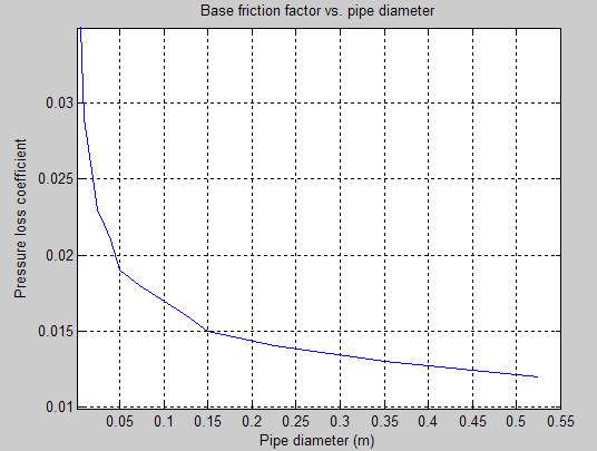
The base friction factor coefficient is determined according to the following table.

Note
Friction factors for pipes with diameters greater than 525 mm are determined by extrapolation.
The correction coefficient accounting for the bend curvature is determined according to the next table.

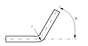
The bend curvature relative radius is calculated as
r = bend radius /
pipe diameter
Note
For pipes with the bend curvature relative radius value outside the range of 1 >
r > 24, correction coefficients are determined by
extrapolation.
Correction for non-90o bends is performed with the empirical formula (see [2], Fig. 4.6):
where
| α | Bend angle in degrees (0 ≤ α ≤ 180) |

Connections A and B are conserving hydraulic ports associated with the block inlet and outlet, respectively.
The block positive direction is from port A to port B. This means that the flow rate is positive if fluid flows from A to B, and the pressure differential is determined as .
Warning
The formulas used in the Pipe Bend block are very approximate, especially in
the laminar and transient flow regions. For more accurate results, use a combination of the
Local Resistance block with a table-specified K=f(Re)
relationship and the Hydraulic Resistive Tube block.
Basic Assumptions and Limitations
Fluid inertia and wall compliance are not taken into account.
The bend is assumed to be made of a clean commercial steel pipe.
Parameters
- Pipe diameter
The internal diameter of the pipe. The default value is
0.01m.- Bend radius
The radius of the bend. The default value is
0.04m.- Bend angle
The angle of the bend. The value must be in the range between 0 and 180 degrees. The default value is
90deg.- Internal surface roughness height
Roughness height on the pipe internal surface. The parameter is typically provided in data sheets or manufacturer's catalogs. The default value is
1.5e-5m, which corresponds to drawn tubing.- Critical Reynolds number
The maximum Reynolds number for laminar flow. The value of the parameter depends on the orifice geometrical profile. You can find recommendations on the parameter value in hydraulics textbooks. The default value is
350.- Fluid compressibility
Dynamic compressibility setting. Select
Onto make the fluid density dependent on pressure and temperature. SelectOffto treat the fluid density as a constant. Dynamic compressibility impacts the transient response of the fluid at small time scales and can slow down simulation.- Initial liquid pressure (gauge)
Gauge pressure in the pipe bend at time zero. The default value is
0Pa.
Global Parameters
Parameters determined by the type of working fluid:
Fluid density
Fluid kinematic viscosity
Use the Hydraulic Fluid block or the Custom Hydraulic Fluid block to specify the fluid properties.
Ports
The block has the following ports:
AHydraulic conserving port associated with the bend inlet.
BHydraulic conserving port associated with the bend outlet.
References
[1] Flow of Fluids Through Valves, Fittings, and Pipe, Crane Valves North America, Technical Paper No. 410M
[2] George R. Keller, Hydraulic System Analysis, Published by the Editors of Hydraulics & Pneumatics Magazine, 1970
Extended Capabilities
Version History
Introduced in R2006bSee Also
Elbow | Gradual Area Change | Local Resistance | Hydraulic Resistive Tube | Sudden Area Change | T-junction
