Main Content

Sensorless Six-Step Commutation

Use six-step commutation to run a BLDC motor or PMSM using sensorless control

Since R2025a

Libraries:
Motor Control Blockset / Controls / Controllers

Description

The Sensorless Six-Step Commutation block uses six-step commutation to run a Brushless DC Motor (BLDC) motor or Permanent Magnet Synchronous Motor (PMSM) using sensorless control.

The block uses VabcMeas (measured terminal voltages) and VdcMeas (DC bus voltage) inputs to generate duty cycles for the six switches of inverter. You can select the operating mode as Alignment, Alignment -> Open-loop run, or Alignment -> Open-loop run -> Controlled commutation.

The Alignment phase in sensorless six-step commutation is used to initialize the rotor position of a BLDC motor, so that it can start correctly. The method applies specific voltages to the motor phases A and B, so that the rotor is forced to align with a known position (-30 electrical degrees with respect to phase A).

The Open-loop run phase in sensorless six-step commutation is used to reach a speed for the motor to generate sufficient back-EMF that can be used to detect the zero crossings of back-EMF (the recommended value for this speed can vary from 10 - 30% of motor rated speed). In this phase, you need to provide the voltage magnitude (Open-loop duty cycle) and acceleration as inputs. The frequency of applied voltage (or motor speed) increases linearly according to another set of inputs – ramp-up time and target open loop speed. Initially, a voltage is applied to all three phases, with a slow increase in frequency of the applied voltage. The rotor is expected to synchronize with applied voltage, and it continues to rotate at the specified speed. The block acquires terminal voltage and detects zero crossings of motor back-EMF. These detections are used to compute the actual speed of the motor and indicate readiness to move to controlled commutation state.

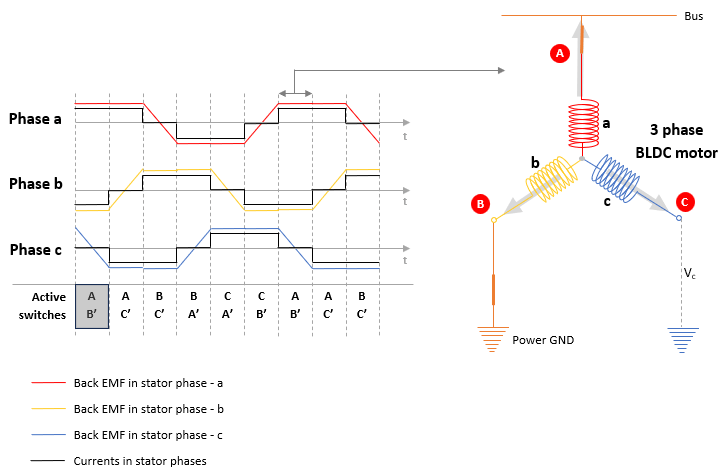
In the final phase, Controlled commutation, speed and six-step commutation instants are accurately determined from back-EMF zero cross detections. The applied magnetic field leads the rotor by 60-120 degrees (electrical). This behavior is the same as what can be achieved even when using a hall sensor with six-step commutation. The block uses the zero-crossing point of the back-EMF in the dormant motor phase during each 60-degree sector to determine the moment of activation of dormant phase. It adds a 30-degree offset to the zero-crossing point to turn ON the dormant phase (and turn OFF one of the other phases) at correct moment in time.

Note

By default, the block uses the Controlled commutation phase, which uses default pre-populated values for the various parameters. However, you can follow a sequential workflow by using the option to select the other two phases in the same block, which also helps to obtain derived values for all required parameters, specific to your motor, prior to moving to Controlled commutation phase. For example, you can follow this sequence:

  1. Select Alignment phase and deploy the model to run the motor and obtain derived values related to that phase.

  2. Select Open-loop run phase, use derived values from Alignment phase, and deploy the model to run the motor and obtain derived values related to Open-loop run phase.

  3. Select Controlled Commutation phase, use derived values from Alignment and Open-loop run phases, and deploy the model to run the motor in controlled commutation.

Examples

Ports

Input

expand all

Direction of motor rotation.

Data Types: int16

Measured motor terminal voltages (A,B,C) in volts.

Data Types: single | double | fixed point

Measured DC bus voltage in volts.

Data Types: single | double | fixed point

Reference duty cycle input, which is the output of a speed controller or current controller, in the range 0 to 1.

Data Types: single | double | fixed point

Filter delay time and demagnetization time delay (in seconds), specified as a vector, to be considered. This input compensates for the delay introduced in the measurement of voltages (Vabc) due to the use of hardware or software filters, and for the delay needed to prevent detection of spurious zero crossings.

Dependencies

To enable this port, set Compensation for filter delay (Tf) and demagnetization time (Td) parameter to Input port.

Data Types: single | double | fixed point

Enable or disable the block to perform six-step commutation.

Data Types: Boolean

Output

expand all

Stator phase a, b, and c voltages that drive the motor. The data type is the same as for the input DutyRef.

Data Types: single | double | fixed point

Angular speed detected based on the BEMF (back EMF) zero cross detection.

Data Types: single | double | fixed point

Signal information for testing or debugging, to be accessed using dot notation. The signals of this bus output can be accessed using a bus selector, and it provides these values:

  • Info.StateAlignment – returns 1 if the motor is in the Alignment phase (the Operating mode selection in the block is set to Alignment)

  • Info.StateOpenLoop – returns 1 if the motor is in open-loop run (the Operating mode selection in the block is set to Alignment -> Open-loop run and the motor has started running in open-loop)

  • Info.StateAcquisition – returns 1 if the motor is in open-loop run (the Operating mode selection in the block is set to Alignment -> Open-loop run) and the controller is acquiring signals for detecting back-EMF zero-crossings

  • Info.OpenLoopSwitchState – returns information on the state of active switches in the inverter. This signal provides information on which two switches of the inverter are turned-on. The six step commutation has six states (numbered from 1 - 6) that are applied over one electrical cycle.

  • Info.EnableCommutation – returns 1 if the motor is in controlled commutation by detecting zero-crossings properly (the Operating mode selection in the block is set to Alignment -> Open-loop run -> Controlled commutation)

  • Info.Counter30deg – Counter that holds number of time samples needed to detect 30 electrical degrees at a given motor speed

  • Info.FilterDelayinSamples – Filter delay input converted to number of time samples n (n = Tf/Ts where Ts is block sample time, and Tf is time delay due to voltage sense filter)

  • Info.DemagTimeinSamples – Demagnetization time input converted to number of time samples n (n = Td/Ts where Ts is block sample time, Td is demagnetization time)

Data Types: uint16

Indication that block is transitioning from open-loop to controlled six-step commutation when back-EMF zero-crossing detections are successful (returns 1).

Data Types: Boolean

Parameters

expand all

Option to determine initial rotor position by checking rotor alignment. Selecting this option opens the Alignment pane to specify the related parameters.

The motor alignment stage energizes two phases of the motor (phases a and b). The resulting magnetic field forces the rotor to align at -30 degrees (electrical position) from phase-a axis.

Option to determine rotor position by starting the motor in open-loop. Selecting this option opens the Open loop pane to specify the related parameters.

Running the model after selecting the Alignment -> Open-loop run option energizes the subsequent phases of the motor sequentially (in six-step mode using a pre-defined acceleration) to pull the rotor and run it under a no-load or low-load condition such that it gradually increases the motor speed. The open-loop stage is used to increase the motor speed to a value that generates sufficient back-EMF that can be measured accurately.

Option to determine rotor position by running the motor in closed-loop. Selecting this option opens the Controlled commutation pane to specify the related parameters.

Running the model after selecting the Alignment -> Open-loop run -> Controlled commutation option detects the motor back-EMF zero crossing to accurately generate the six-step commutation pattern (in the form of duty cycles) that is applied to the BLDC motor phases.

After you run a motor using open-loop six-step control and complete speed acquisition, you can run the motor using closed-loop controlled commutation

Number of motor pole pairs.

The fixed time interval (in seconds) between every two consecutive instances of block execution.

Alignment

Duty cycle of voltage to be applied between phases A and B, to align the rotor at -30 degrees (electrical) with respect to phase A (as part of the Alignment phase).

Duration (in seconds) to apply the voltage between phase A and B, to specify the time that the rotor takes to move from the initial unknown position to the known position of -30 degrees with respect to phase a (as part of the Alignment phase). This parameter is dependent on the motor parameters as well as the value of the Alignment duty cycle parameter.

Open-Loop

Duty cycle of voltage to be applied to all three phases, to run the motor in open-loop (as part of the Alignment –-> Open-loop run phase). The voltage must be sufficient enough to pull the rotor and run it under a no-load or low-load condition such that it gradually increases the motor speed.

Target speed (RPM) to be achieved by the rotor to generate a sufficient back-EMF during open-loop run.

Ramp up time (s) to achieve the RPM value that you specified for Target open-loop speed parameter, during open-loop run. Both these parameter values determine the acceleration of the rotor when it starts the open-loop phase.

Speed at which the algorithm starts motor phase voltage acquisition process during open-loop phase. This value defines the speed above which the algorithm must start detecting zero-crossings to compute motor speed. Ensure that you set this value to be less than that of Target open-loop speed parameter.

Controlled Commutation

Minimum number of speed samples to be considered, for comparing with the speed defined for Open-loop speed to initiate transition to controlled commutation parameter, before transitioning to controlled commutation phase.

Defining a correct value for this parameter ensures that the motor reaches and stay above a minimum speed for generating sufficient back-EMF (for accurate detection of zero-crossing points) before transitioning to the closed-loop control.

Specify one of the methods to define compensation for Tf and Td. Specifying time delays allows the block to compensate for these known time delays introduced in measured voltage. The time delay would otherwise result in delayed zero-crossing detection and also leads to generation of incorrect commutation pattern potentially resulting in a stalled motor.

Time delay to compensate for delay due to a hardware or software filter used for voltage measurement (the type of filter can be different and the filter may reside in circuit or in code). Providing a correct value to this parameter ensures that the block is able to generate accurate commutation sequences without phase delays.

Time during which the demagnetization of winding is occurring and voltage signals need not be acquired, to prevent spurious zero-crossing detection. It is also defined as the waiting period between the time instance at which stator phase demagnetization occurs and the time instance when back-EMF crosses above the line of zero-crossing.

Extended Capabilities

expand all

C/C++ Code Generation
Generate C and C++ code using Simulink® Coder™.

Fixed-Point Conversion
Design and simulate fixed-point systems using Fixed-Point Designer™.

Version History

Introduced in R2025a