Sensorless Speed Control of BLDC Motor Using Six-Step Commutation
This example uses 120-degree conduction mode to implement the six-step commutation technique to control the speed of a three-phase brushless DC (BLDC) motor. The example uses the mechanical speed along with the duty cycles generated by the Sensorless Six-Step Commutation block to control three-phase stator voltages, and therefore, control the rotor speed.

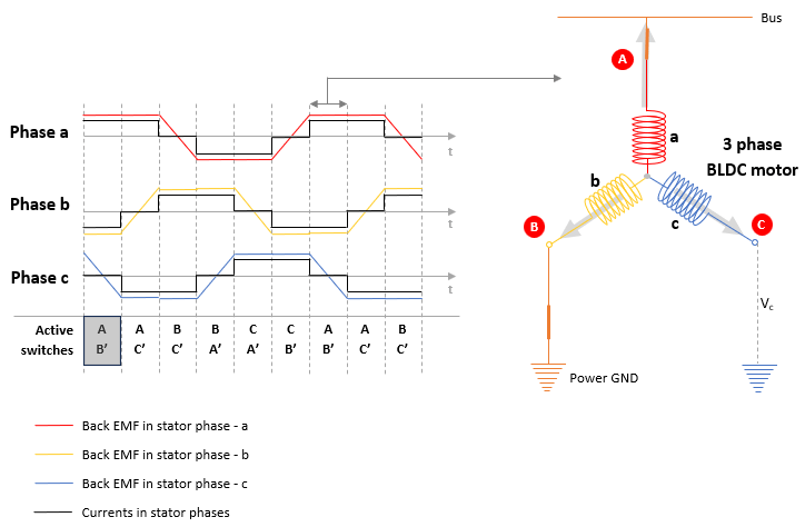
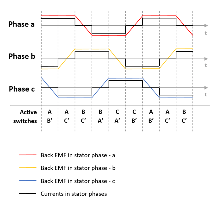
The six-step commutation algorithm activates or energizes each of the three motor phases as shown in the preceding figure. The algorithm generates trapezoidal back-EMF in the three-phase stator windings such that for the duration of activation of a stator phase (120 degrees), the back-EMF remains constant.
To generate the right commutation pattern (or duty cycles) that energize each motor phase at the correct moment in time, the six-step commutation algorithm requires position feedback, which can be computed from the back-EMF in the phase windings.
This example uses the measured motor terminal voltage in the dormant (or unexcited) phase of a BLDC motor to determine the switching points for turning ON and OFF motor phases.
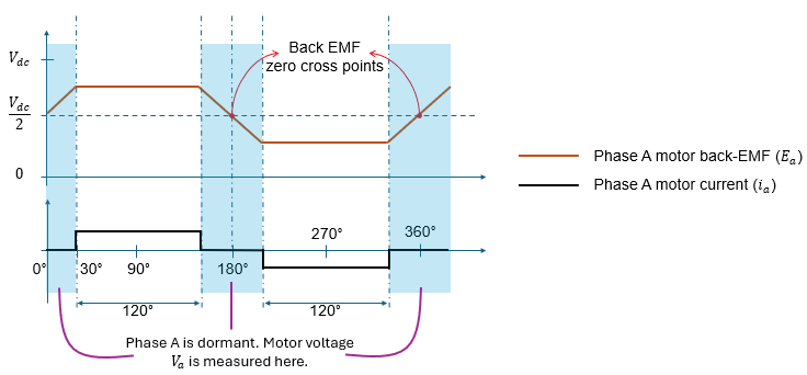
Each 60-degree segment in a 360-degree cycle consists of two energized phases and one dormant phase. During this segment, the dormant phase back-EMF either falls or rises as shown in the following figure.
The Sensorless Six-Step Commutation block uses the zero-crossing point of the back-EMF in the dormant motor phase during each 60-degree sector to determine the moment of activation of dormant phase. It adds a 30-degree offset to the zero-crossing point to turn ON the dormant phase (and turn OFF one of the other phases) at correct moment in time.
Model
The example includes the target model BLDCSensorlessSixStepControl, which supports both simulation and code generation.
Required MathWorks Products
To simulate target model, you need:
Motor Control Blockset
Simscape Electrical
To generate code and deploy model, you need:
Motor Control Blockset
Embedded Coder
C2000 Microcontroller Blockset
Fixed-Point Designer (only needed for optimized code generation)
Required Hardware
The example supports the following hardware configuration:
LAUNCHXL-F28379D controller + BOOSTXL-DRV8305 inverter
For connections related to these hardware configurations, see LAUNCHXL-F28069M and LAUNCHXL-F28379D Configurations.
Algorithm
To run a motor using six-step commutation, the example uses a starting procedure that aligns the rotor and then runs it using open-loop control to generate sufficient back-EMF before transitioning to sensorless six-step commutation.
The example operates the motor in the following three stages, sequentially :
Stage 1 – Motor alignment
Stage 2 – Open-loop run
Stage 3 – Controlled commutation
Note: The example follows a workflow that allows you to calibrate the sensorless six-step algorithm to run any generic BLDC motor.
Update Motor Parameters
1. Obtain the motor parameters. The Simulink® model uses default motor parameters that you can replace with the values from either the motor datasheet or other sources.
However, if you have the motor control hardware, you can estimate the parameters for the motor that you want to use, by using the Motor Control Blockset's Parameter Estimation tool. For instructions, see Estimate PMSM Parameters Using Recommended Hardware.
The Parameter Estimation tool updates the motorParam variable (in the MATLAB® workspace) with the estimated motor parameters.
2. If you obtain the motor parameters from the datasheet or other sources, update the motor parameters and inverter parameters in the model initialization script associated with the Simulink® models. For instructions, see Estimate Control Gains and Use Utility Functions.
% Run this section to open model init script to update motor parameters
open("BLDCSensorlessSixStepControlData.m");
Note: To work with this example, the primary motor parameters needed are the number of motor pole pairs and the rated speed (base speed) of the motor.
Stage 1 – Motor Alignment
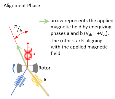
During the motor alignment stage, the example algorithm energizes two phases of the motor (phases a and b). The resulting magnetic field forces the rotor to align at 30-degrees (electrical position) from phase-a axis.
Run the following code to open the target model and configure it to run the motor alignment stage.
open("BLDCSensorlessSixStepControl.slx");
Mode = 1; % Set Alignment mode
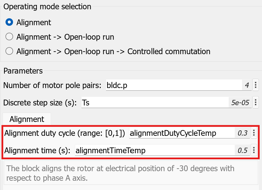
Running the command Mode = 1 enables the "BLDCSensorlessSixStepControl/Commutation Control/Commutation Control and Speed Measurement/ModeSelector/Mode1_Alignment" subsystem variant, which uses the Sensorless Six-Step Commutation block. The block has the Operating mode selected as Alignment and has the following parameter values configured.
Alignment duty cycle (range: [0,1]) – alignmentDutyCycleTemp
Alignment time (s) – alignmentTimeTemp
1. Run the following code to configure the Alignment parameters.
Note: Update the values of the variables alignmentDutyCycleTemp and alignmentTimeTemp according to the motor you are using before running the following code.
initialMotorPosition =0; % Enter a value between 0 - 360 degrees (Electrical) alignmentDutyCycleTemp =
0.3; % Range 0-1 alignmentTimeTemp =
0.5; % Alignment time in seconds
The example uses the alignmentDutyCycleTemp variable to compute and apply a DC voltage (proportional to alignmentDutyCycleTemp) to the phases a and b for the time that you specify using the alignmentTimeTemp variable. Increasing alignmentDutyCycleTemp increases the applied stator voltages, and therefore increases the DC current drawn by the motor. Increasing alignmentTimeTemp increases the time duration for which the DC voltage is applied to the motor. The value of alignmentTimeTemp can be determined using simulation or by deploying the code on hardware and taking measurements from the same.
alignmentTimeTemp is the time that the rotor takes to move from an initial unknown position to the known position of -30 degrees with respect to phase a. The alignmentTimeTemp is dependent on the motor parameters as well as the value of the alignmentDutyCycleTemp variable.
2. Simulate the target model to perform the alignment and determine the alignmentTimeTemp value for the set alignmentDutyCycleTemp value.
3. Alternatively, click the Build, Deploy & Start button available in the Hardware tab to deploy the target model to the controller board. Open the host model to control the motor and measure the alignmentTimeTemp value required for the motor.
Note: To measure alignment time on hardware, the example model and the host model need to be modified to use a physical sensor (such as quadrature encoder sensor) available in your motor along with the LAUNCHXL-F28379D controller board.

Stage 2 – Open-Loop Run
After the algorithm aligns the rotor, it energizes the subsequent phases of the motor sequentially (in six-step mode using a pre-defined acceleration) to pull the rotor and run it under a no-load or low-load condition such that it gradually increases the motor speed. The example uses open-loop stage to increase the motor speed to a value that generates sufficient back-EMF that can be measured accurately.
Run the following code to define the obtained alignment parameters and configure the target model for motor alignment and open-loop execution.
open("BLDCSensorlessSixStepControl.slx");
Mode = 2;                                      % Set Alignment + Open Loop mode
initialMotorPosition = 0;
alignmentDutyCycle = alignmentDutyCycleTemp;   % Obtained from previous step
alignmentTime = alignmentTimeTemp;             % Obtained from previous step
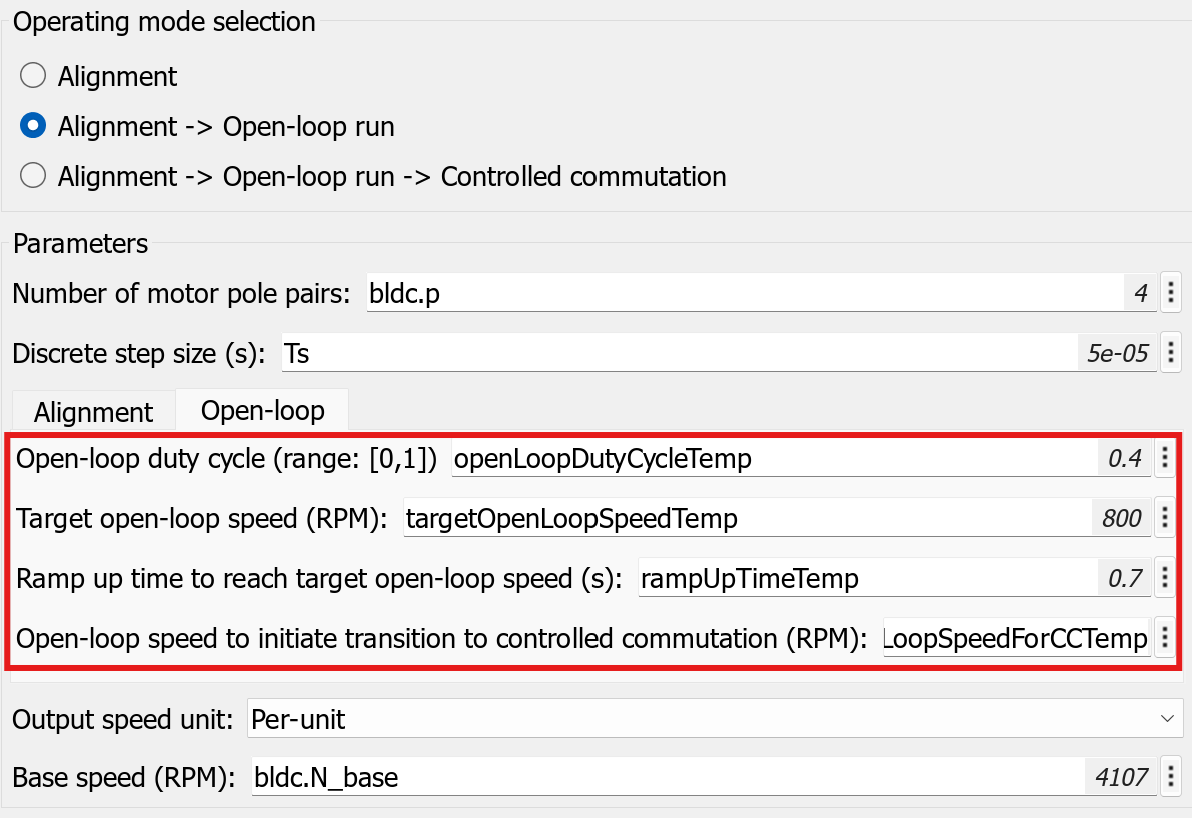
Running the command mode = 2 enables the BLDCSensorlessSixStepControl/Commutation Control/Commutation Control and Speed Measurement/ModeSelector/Mode2_AlignAndOpenLoop subsystem variant, which uses the Sensorless Six-Step Commutation block. The block has the operating mode selected as Alignment -> Open-loop run and has the following values configured for the parameters.
Open-loop duty cycle (range: [0,1]) – openLoopDutyCycleTemp
Target open-loop speed (RPM)– targetOpenLoopSpeedTemp
Ramp up time to reach target open-loop speed (s) – rampUpTimeTemp
Open-loop speed to initiate transition to controlled commutation (RPM) - openLoopSpeedForCCTemp
The targetOpenLoopSpeedTemp and rampUpTimeTemp parameters define the acceleration that the example uses to attain the target open-loop speed.
Note: If the acceleration (targetOpenLoopSpeedTemp/rampUpTimeTemp) value is too high or if the openLoopDutyCycleTemp is too low, the motor can fail to run using open-loop control or the motor may run for a short time before stalling. Therefore, ensure that you set these three parameters appropriately for your motor.
Open-loop speed to initiate transition to controlled commutation (RPM) (openLoopSpeedForCCTemp) - After reaching this speed, the algorithm starts motor phase voltage acquisition process. From the measured dormant motor phase voltages, the back-EMF zero-crossings are detected and the speed of the motor is computed. A back-EMF zero-crossing occurs every 60-degrees (electrical), and the algorithm runs a counter to count the number of time samples between two consecutive zero crossings and uses this counter value to determine the motor speed. The openLoopSpeedForCCTemp variable defines the speed above which the example algorithm must start detecting zero-crossings to compute motor speed. Ensure that you set this value to be less than that of targetOpenLoopSpeedTemp.
1. Run the following code to configure the open-loop control parameters.
Note: Update the values of the variables openLoopDutyCycleTemp, targetOpenLoopSpeedTemp, rampUpTimeTemp, and openLoopSpeedForCCTemp according to the motor you are using before running the following code.
openLoopDutyCycleTemp =0.4; targetOpenLoopSpeedTemp =
800; rampUpTimeTemp =
0.7; openLoopSpeedForCCTemp =
500;
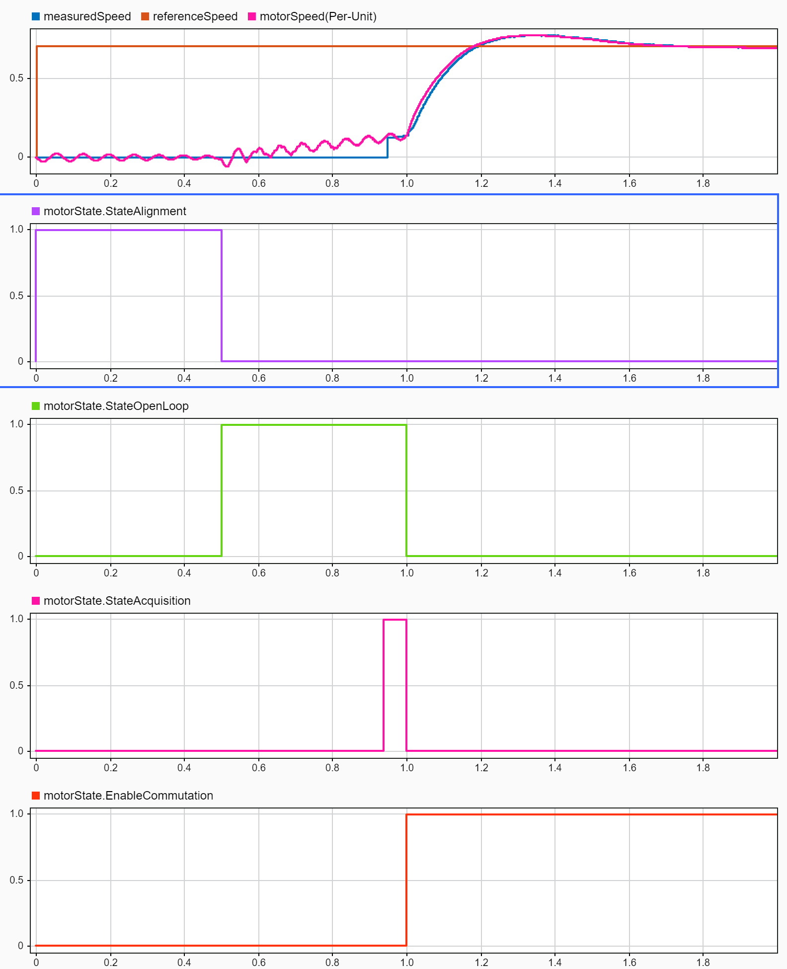
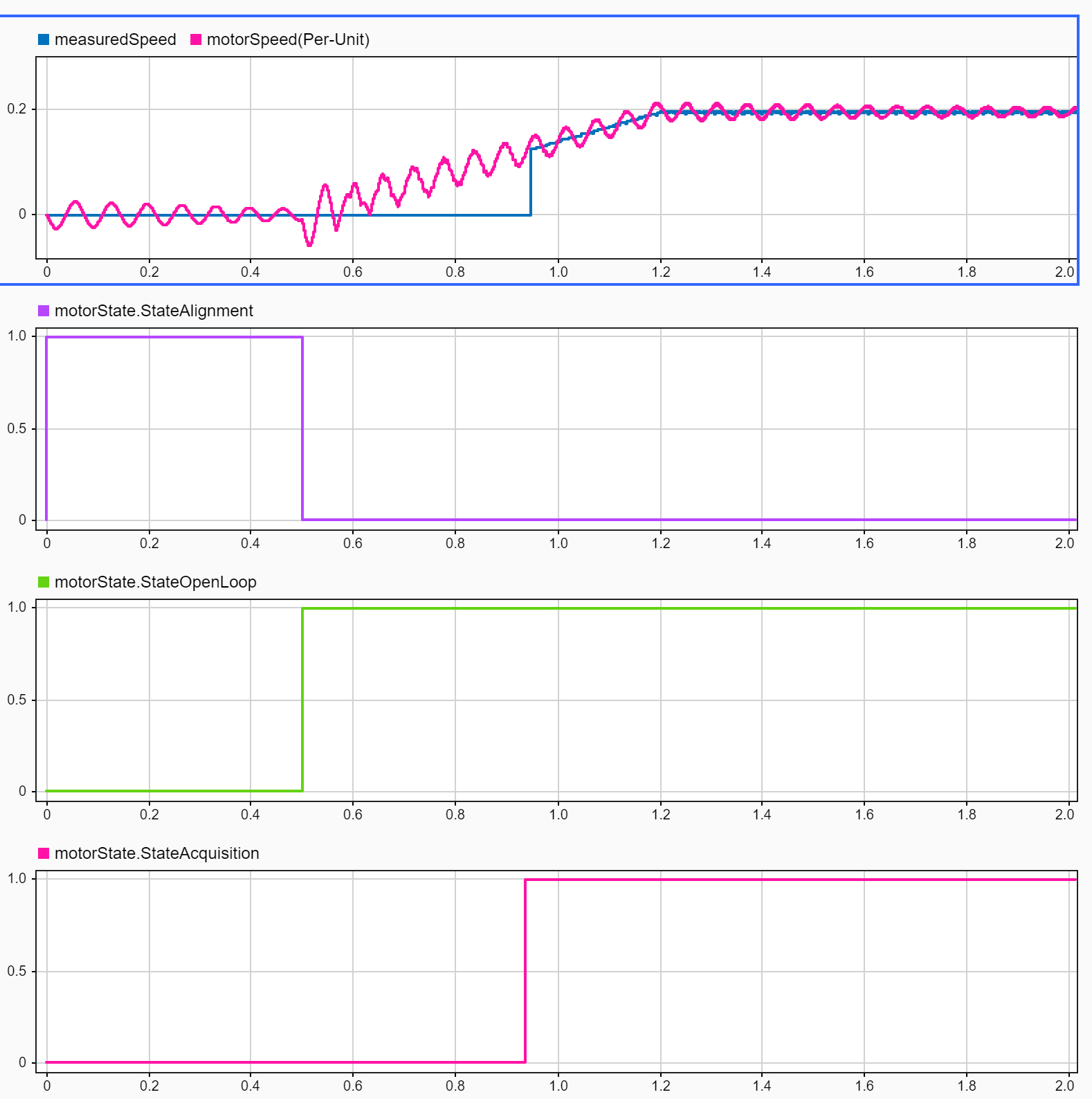
2. Simulate the target model to run the motor using open-loop control in simulation. Modify the preceding parameters and re-run the target model to monitor the variation in the motor speed. (See below picture)
3. Alternatively, click the Build, Deploy & Start button available in the Hardware tab to deploy the target model and check the set parameters by running the motor on hardware. Open the host model to control the motor and monitor the motor speed. Observe that the motor is physically spinning and check that its speed increases linearly till it reaches the set speed of targetOpenLoopSpeedTemp.
Tip: For hardware deployment, if you have a speed sensor (such as quadrature encoder sensor or hall sensor), you can use it to compare the computed speed value against the speed sensor output.
After you run simulation, you can modify openLoopSpeedForCCTemp to an appropriate value that meets the application requirements. It is recommended that you set this variable (openLoopSpeedForCCTemp) to 10% of the motor rated speed.
Note: Before you transition to controlled commutation, configure the openLoopSpeedForCCTemp variable appropriately to ensure that sufficient back-EMF is generated at this speed that can be detected accurately.
It is recommended that you set the Target open-loop speed (RPM) (targetOpenLoopSpeedTemp) parameter to 20% of the motor rated speed.
If you are using a different motor than the one in the example, then at the end of this stage (provided the parameters are set correctly), the motor must be able to align and run in open loop till the Target open-loop speed (RPM) is achieved along with the speed measurement being active.
Stage 3 – Controlled Commutation
After you run a motor using open-loop six-step control and complete speed acquisition, you can run the motor using closed-loop controlled commutation. The example uses Sensorless Six-Step Commutation block which detects the motor back-EMF zero crossing to accurately generate the six-step commutation pattern (in the form of duty cycles) that is applied to the BLDC motor phases. The block also gives measured motor speed as a output - which is used to control the speed of the motor.
Run the following code to define the controlled commutation parameters and configure the target model for motor alignment, open-loop execution, and controlled commutation.
open("BLDCSensorlessSixStepControl.slx");
Mode = 3; % Set Alignment + Open Loop + Controlled commutation mode
initialMotorPosition = 0;
% Below variables are obtained from previous steps
alignmentDutyCycle = alignmentDutyCycleTemp;
alignmentTime = alignmentTimeTemp;
openLoopDutyCycle = openLoopDutyCycleTemp;
targetOpenLoopSpeed = targetOpenLoopSpeedTemp;
rampUpTime = rampUpTimeTemp;
openLoopSpeedForCC = openLoopSpeedForCCTemp;
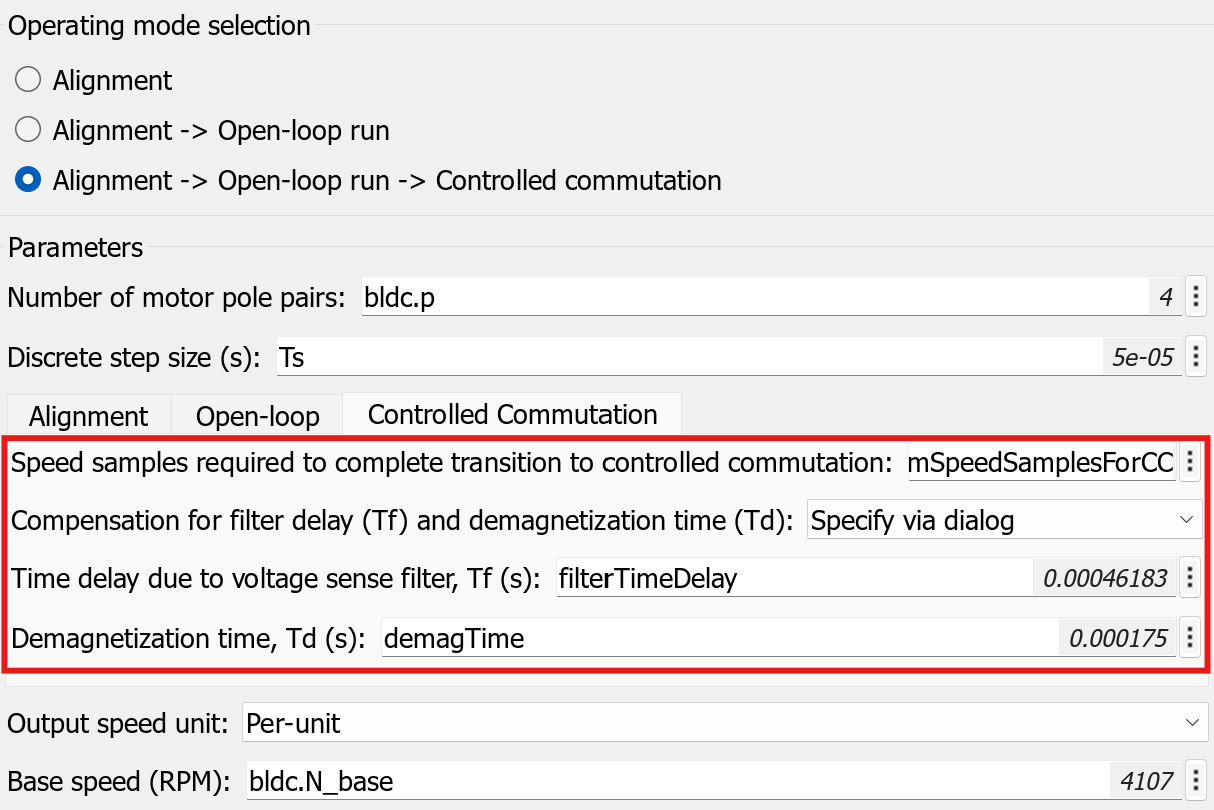
Running the command mode = 3 enables the BLDCSensorlessSixStepControl/Commutation Control/Commutation Control and Speed Measurement/ModeSelector/Mode3_AlignOpenLoopAndCommutation subsystem variant, which uses the Sensorless Six-Step Commutation block. The block has the operating mode selected as Alignment -> Open-loop run -> Controlled commutation and has the following parameter configuration.
Speed samples required to complete transition to controlled commutation – numSpeedSamplesForCC
Compensation for filter delay (Tf) and demagnetization time (Td) – Specify via dialog
Time delay due to voltage sense filter, Tf (s) – filterTimeDelay
Demagnetization time, Td (s) – demagTime
During the voltage acquisition process, which starts when motor speed is greater than Open-loop speed to initiate transition to controlled commutation (RPM) parameter in the open-loop run phase, the example starts to compute the motor speed based on the detected zero-crossings of motor back-EMF. The example successfully transitions to the closed-loop controlled commutation stage only if a minimum number of consecutive speed samples are greater than Open-loop speed to initiate transition to controlled commutation (RPM). The Speed samples required to complete transition to controlled commutation parameter defines this minimum number of samples.
This process ensures that the motor reaches and stay above a minimum speed for generating sufficient back-EMF (for accurate detection of zero-crossing points) before transitioning to the closed-loop control.
1. Run the following code to configure the closed-loop control parameters.
Note: Update the values of the variables numSpeedSamplesForCC, filterTimeDelay, and demagtime according to the motor you are using before running the following code.
numSpeedSamplesForCC =10; filterTimeDelay =
0.00046183; demagTime =
0.000175;
Use the numSpeedSamplesForCC variable to specify the number of consecutive measured speed samples that must exceed openLoopSpeedForCC, for the example to switch over to controlled commutation after the open loop run.
Voltage Measurement Circuit Filter Delay
Usually the motor phase voltage measurement includes hardware or software filters to attenuate switching noise. These filters can introduce a time delay (also known as group delay) in the measured motor phase voltage signal resulting in delayed zero-crossing detection, which leads to generation of incorrect commutation pattern potentially resulting in a stalled motor.
The BOOSTXL-DRV8305 inverter uses a first order RC filter (with a filter time constant of 461.83µs) in the voltage measurement circuit. The filterTimeDelay variable specifies this time delay to the example algorithm. The algorithm uses this variable to compensate for the time delay due to the filter used in the voltage measurement circuit, which enables the algorithm to accurately detect the zero-crossing points as well as energize motor phases at right moment of time. Therefore, updating this variable enables the example algorithm to generate accurate commutation sequences without phase delays.
Because this example uses a motor speed that is significantly lower than the cut-off frequency of the voltage measurement circuit filter, the example assumes that group delay is approximately equal to the filter time constant. Therefore, for the LAUNCHXL-F28379D controller card + inverter combination, the example uses a filter delay value of 461.83µs.
In some applications, the group delay value can vary with the motor speed depending on the cut-off frequency of the filter. In such cases, you can set the parameter Compensation for filter delay (Tf) and demagnetization time (Td) of the Sensorless Six-Step Commutation block to Input port, which enables the example algorithm to detect the group delay value in real-time through an input port.
Demagnetization Time
When the example algorithm commutates a motor phase (for example, switches from phase A to phase B), the residual falling currents in phase A causes a temporary drop in measured motor back-EMF due to demagnetization of phase A winding. This voltage drop can go below the line of zero-crossing or Vdc/2 as shown in the following figure.

The measured motor back-EMF eventually rises above the line of zero-crossing and then touches the actual zero-crossing point (at Tz in the above figure). Therefore, the measured back-EMF has three zero-crossing points during the 60-degree segment, the first two due to demagnetization of commuting phase.
Due to such behavior, the sensorless algorithm in the example should wait until the measured back-EMF crosses above the line of zero-crossing, before it can start detecting the actual zero-crossing point. This waiting period (between the time of stator phase demagnetization and the time when back-EMF crosses above the line of zero-crossing) is known as demagnetization time. To ensure that the example algorithm correctly detects and uses the second instance of zero-crossing, you must specify demagnetization time (Td) using the demagTime variable. During the demagnetization time (Td), also known as blanking time, the algorithm does not acquire voltage signals to prevent spurious zero-crossing detection.
Use demagTime variable to specify a maximum time value that is greater than or equal to Td but less than the actual time of zero-crossing (Tz) to ensure accurate commutation and speed measurement. In some applications, the demagnetization time value can change in real-time with varying motor load conditions. In such cases, you can set the parameter Compensation for filter delay (Tf) and demagnetization time (Td) of the Sensorless Six-Step Commutation block to Input port, which enables the example algorithm to accept the demagnetization time value in real-time through an input port.
2. Simulate the target model to run the motor in speed control using sensorless six step commutation in simulation. If needed, modify the preceding parameters and monitor the variation in the motor speed.
3. Click the Build, Deploy & Start button available in the Hardware tab to deploy the target model and calibrate the closed-loop execution on the hardware. Open the host model to control the motor speed.
Note: As soon as the Sensorless Six-Step Commutation block enters the controlled commutation stage, it turns the Comstatus output port to high. Which is used to enable the speed controller and run the motor in closed-loop speed control.