Design Current Controller Subsystem
Use these steps to design the current controller subsystem:
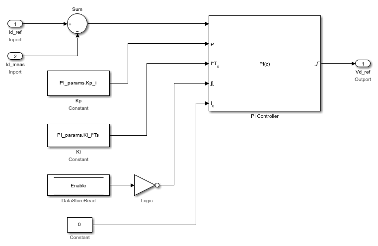
From the Motor Control Blockset™ library in the Simulink® Library Browser, use the PI Controller block (in the Controls/Controllers library) to design the d-axis and q-axis current control. For example, this image shows the d-axis current controller subsystem.
The MATLAB® function
mcb.getPIControllerParameters(in the model initialization script) calculates the PI control gains for the d-axis and q-axis current controller and the speed controller. For details about calculation of the controller gains, see Estimate Control Gains and Tune Control Parameters. For example, see the model initialization script filemcb_pmsm_foc_qep_f28379d_data.m(used in the example Field-Oriented Control of PMSM Using Quadrature Encoder) that uses a sampling time (Ts) of50μs.In the subsystem diagram, the Enable variable is a Data Store Memory used to reset the controller. Adding Enable variable is optional.
The subsystem also uses three constant blocks with these values:
PI_params.Kp_i
PI_params.Ki_i*Ts
0
Create a similar subsystem for the q-axis current PI controller. Integrate the subsystems for d-axis and q-axis PI controllers into a single subsystem (Current_Controllers) that controls the d-axis and q-axis currents.
Add the Clarke Transform, Park Transform, Inverse Park Transform, and PWM Reference Generator blocks from the
Motor Control
                            Blockset/Controls/Math Transforms
library to the Current_Controllers subsystem (that you created in step 1) as shown in this figure.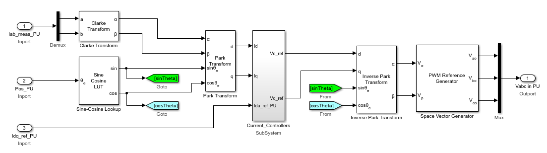
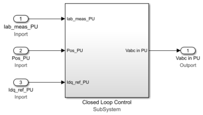
Integrate the components that you created in step 2 into a single subsystem (Closed Loop Control that implements closed loop field-oriented control) as shown in this figure.
Create an Output Scaling subsystem to scale the Pulse Width Modulation (PWM) outputs. This subsystem outputs the normalized PWM duty cycles (
0-1) for the plant model.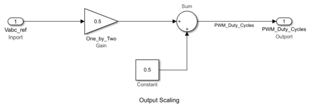
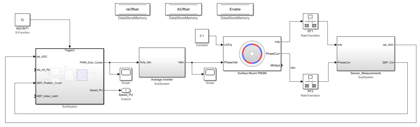
Create a new subsystem by integrating the current scaling (Calculate Phase Currents), QEP position decoding (Calculate Position and Speed), Closed Loop Control, and Output Scaling subsystems. Add the Trigger block from the
Simulink/Ports & Subsystemslibrary to this subsystem and set the Trigger type parameter tofunction-call.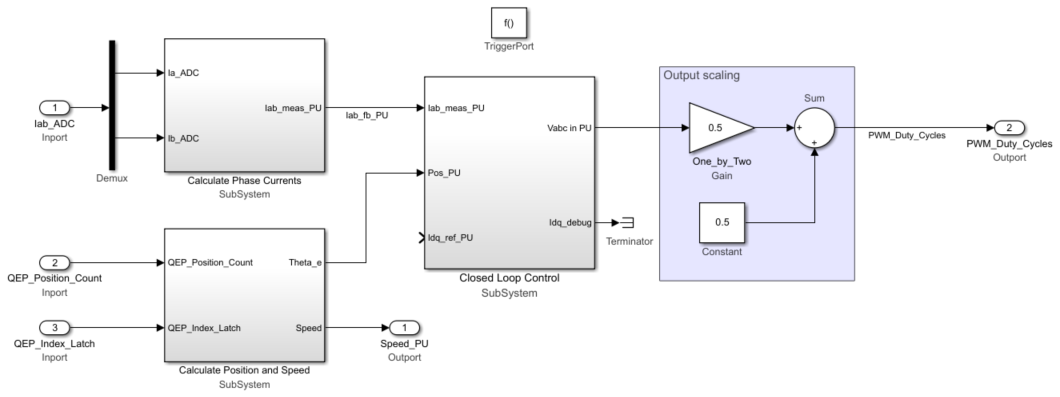
Add a Function-Call Generator block from the
Simulink/Ports & Subsystemslibrary to the subsystem created in step 5. Set the Sample time parameter of the block to equal the control-loop sample time, Ts (that has a default value of50e-6s).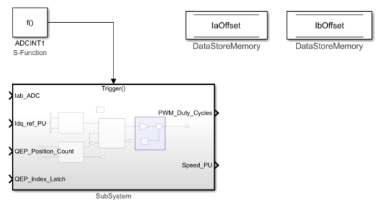
Integrate the plant model and the controller subsystem that you created in step 6. For detailed steps on how to create a plant model for a motor control system, see Creating Plant Model Using Motor Control Blockset.