Phase Noise at PLL Output
This example shows how to predict the phase noise at the output of a phase-locked loop (PLL), simulate the PLL using the PLL Testbench, and compare the simulation results to theoretical predictions.
This example demonstrates three phase noise effects, individually or combined, depending on the configuration you choose:
reference modulation or phase noise,
VCO phase noise,
or VCO phase noise subsampled by the feedback prescaler.
Open the model PllPhaseNoiseExample.slx.
open_system('PllPhaseNoiseExample.slx');
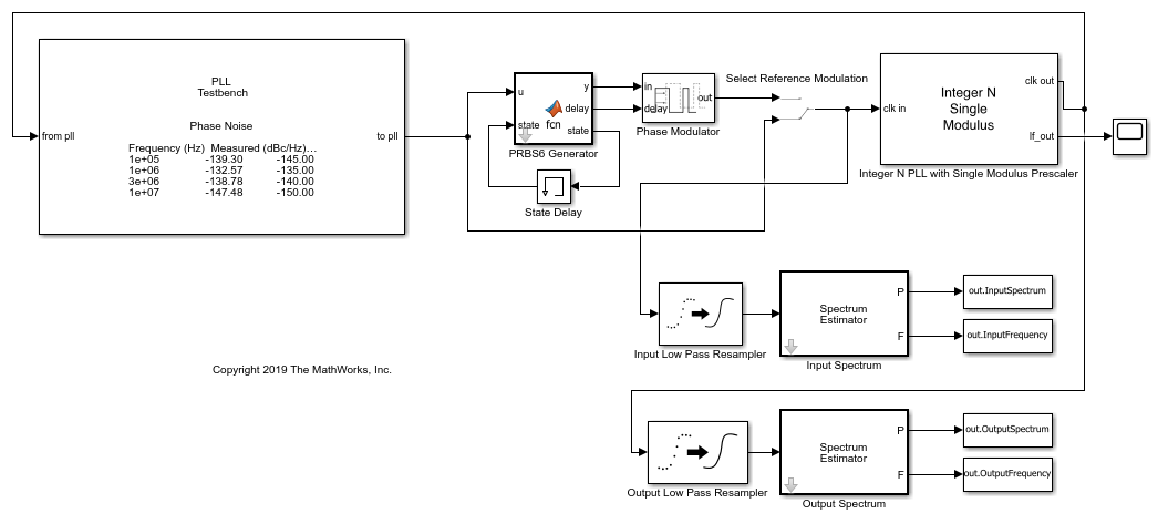
This example uses an Integer N PLL with Single Modulus Prescaler block from Mixed Signal Blockset™.
The PLL Testbench generates the reference input signal for the PLL and measures the phase spectral density at the output of the PLL.
The optional PRBS6 reference phase modulation in this model is used to contrast the response to reference phase variation with the response to VCO phase noise.
The low pass resamplers at the inputs to the spectrum estimators are anti-aliasing filters. These filters convert the variable step discrete signals to the fixed step discrete signals required by the spectrum estimators.
The spectra of the PLL input and output signals are estimated and logged in the base workspace so that you can compare the simulation results to the results of the theoretical calculations.
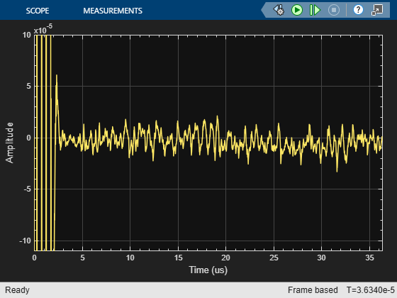
The oscilloscope in the example model provides a progress indicator for the simulation.
To evaluate the behavior of the PLL under a variety of conditions, use a separate workspace file for each different set of conditions. This example provides five such supporting .mat files. All of them produce the same loop transient response.
Baseline.mat- As close to ideal as possible. Use to evaluate numerical noise introduced by the model and simulator.ReferenceModulation.mat- Introduce reference phase modulation. Use to evaluate the phase transfer function of the PLL.VCOPhaseNoise.mat- Introduce VCO phase noise and a prescaler ratio equal to one. Use to evaluate the PLL control loop's error function.InbandPhaseNoise.mat- Introduce VCO phase noise and a prescaler ratio greater than one. Use to evaluate the effect of the prescaler ratio on the PLL control loop's error function.TotalPhaseNoise.mat- All phase noise sources are enabled, and the prescaler ratio is greater than one.
Theoretical Calculations
This section shows how to calculate the expected response of the PLL.
The target loop bandwidth of the PLL is 2 MHz with a 45 degree phase margin. The loop filter components are scaled to practical level and the charge pump output current is scaled by the same factor to maintain the same loop dynamics.
The function getPllLoopResponse calculates the loop gain as a function of frequency and then calculates the expected response to signals from outside or inside the PLL. Define the input parameters such as charge pump output current, VCO sensitivity, prescaler ratio and passive loop filter component values for the getPllLoopResponse function to use.
PllKphi = 5e-3;     % Charge Pump output current
PllKvco = 100e6;    % VCO sensitivity
PllN    = 70;       % Prescaler ratio
PllR2   = 1.33e3;   % Loop filter resistance for second order response (ohms)
PllR3   = 1.7e4;    % Loop filter resistance for third order response (ohms)
PllR4   = 0;        % Loop filter resistance for fourth order response (ohms)
PllC1   = 1.31e-11; % Loop filter direct capacitance (F)
PllC2   = 1.44e-10; % Loop filter capacitance for second order response (F)
PllC3   = 9.41e-13; % Loop filter capacitance for third order response (F)
PllC4   = 0;        % Loop filter capacitance for fourth order response (F)
The script prepareExpectedSpectra computes the spectral density of the reference phase modulation and the VCO output phase noise. The script then also combines the result with the PLL loop response to obtain the phase noise spectral density at the output of the PLL. The reference phase modulation is a deterministic process for which the amplitude of the spectral components is expressed as a fraction of the carrier amplitude (dBc). In contrast, the VCO phase noise is a stochastic process for which the spectral density is expressed in dBc/Hz.
Define the input parameters for the prepareExpectedSpectra script such as reference input frequency, number of reference cycles per symbol of PRBS6 phase modulation data pattern, amplitude of a single spectral component of the PRBS6 reference phase modulation, resolution bandwidth to evaluate spectra with phase noise, frequency offset vector, and phase noise spectral densities at specified frequency offset.
PllAddPhaseNoise = 'on'; % Enable VCO phase noise
PllFoffset    = [30e3 100e3 1e6 3e6 10e6]; % VCO offset frequencies (Hz)
PllPhaseNoise = [-92 -106 -132 -143 -152]; % VCO output phase noise (dBc/Hz)
CfgSelectRefMod = '0';   % Enable reference phase noise modulation
CfgRef  = 30e6;          % Reference frequency
CfgCyclesPerSymbol = 2;  % Reference cycles per PRBS6 modulation symbol
CfgModLevel   = -110;    % Reference phase modulation level (dBc/Hz)
CfgResBandwidth = 100e3; % PLL Testbench resolution bandwidth
CfgTargetSpectrum = [100e3 -145;1e6 -135;3e6 -140;10e6 -150];
                         % PLL Testbench target phase noise (dBc/Hz)
If the variable WorkspaceFile exists and points to a file that can be loaded, load that file into the workspace. To use a configuration supplied with this example, set the value of WorkspaceFile to the name of the file for that configuration.
if exist('WorkspaceFile','var') && exist(WorkspaceFile,'file')
    load(WorkspaceFile);
end
Analyze the PLL control loop using the getPllLoopResponse function. The outputs of this function are:
LoopFrequency- The frequency points at which the expected responses is calculated.LoopZofs- The transfer impedance of the loop filter as a function of the frequency.LoopGofs- The loop gain from the output of the prescaler to the input of the VCO, including the VCO voltage sensitivity. Note that the prescaler ratio is not included in this output, but is included in the closed loop transfer functions.LoopHofs- The closed loop phase transfer function from the PLL reference input to the PLL output.LoopEofs- The closed loop phase error transfer function with respect to the VCO output.
[LoopFrequency, LoopZofs, LoopGofs, LoopHofs, LoopEofs, LoopPhStep] = ...
    getPllLoopResponse([0,PllR2,PllR3,PllR4],[PllC1,PllC2,PllC3,PllC4], ...
                        PllKphi,PllKvco,PllN);
Organize the computation of expected spectral density to place spectral components directly into the frequency bins.
The workspace variables for the expected spectral density are:
ExpInputFrequency- A vector of frequencies for which the expected input spectrum is calculated (Hz).ExpInputSpectrum- A vector of expected spectrum values at the reference input to the PLL (dBm into a one ohm load at a resolution bandwidth ofCfgResBandwidth).ExpOutputFrequency- A vector of frequencies for which the expected output spectrum is calculated (Hz).ExpOutputSpectrum- A vector of expected spectrum values at the PLL output (dBm into a one ohm load at a resolution bandwidth ofCfgResBandwidth).
prepareExpectedSpectra;
Examine Expected Results
In this section, examine the expected PLL behavior.
Start by looking at the closed loop response of the PLL. Consider three fundamental responses: transient response, transfer function, and error function.
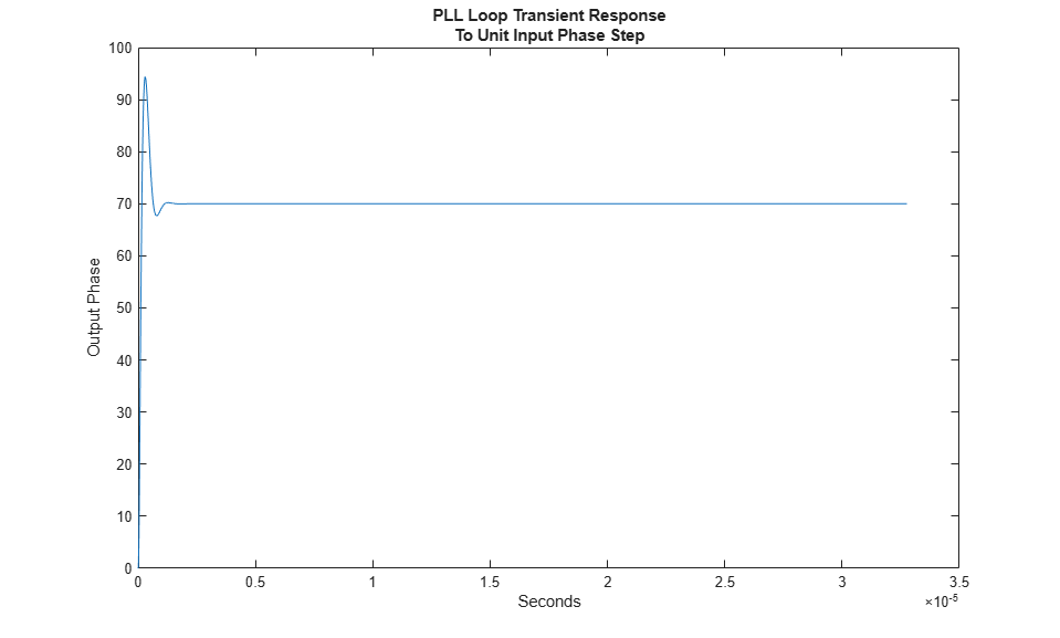
Transient response
In most PLL applications, the loop transient response is most important when the loop is initially acquiring phase lock. For very small initial frequency offsets or for relatively high closed loop bandwidth, the transient response predicts the loop acquisition time reasonably accurately. However, in many cases, the loop transient response only represents the response during phase acquisition, after frequency acquisition has already occurred. This example only addresses the phase acquisition time.
Plot the loop transient response of the PLL.
figure(1);
plot(LoopPhStep.Time,LoopPhStep.Data);
title({'PLL Loop Transient Response';'To Unit Input Phase Step'});
xlabel('Seconds');
ylabel('Output Phase');
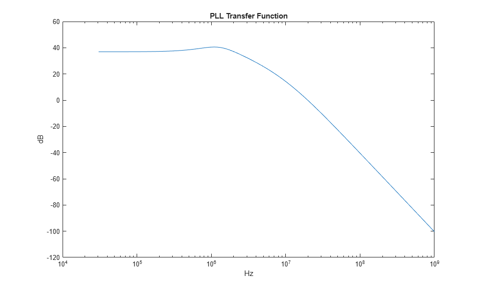
Transfer function
The transfer function from the reference input to the PLL output can be important either when the PLL is expected to track a modulated input very accurately or when it is expected to filter out noise from a noisy input.
Create a log-log plot of the PLL transfer function.
figure(2);
semilogx(LoopFrequency,20*log10(abs(LoopHofs)));
title('PLL Transfer Function');
xlabel('Hz');
ylabel('dB');
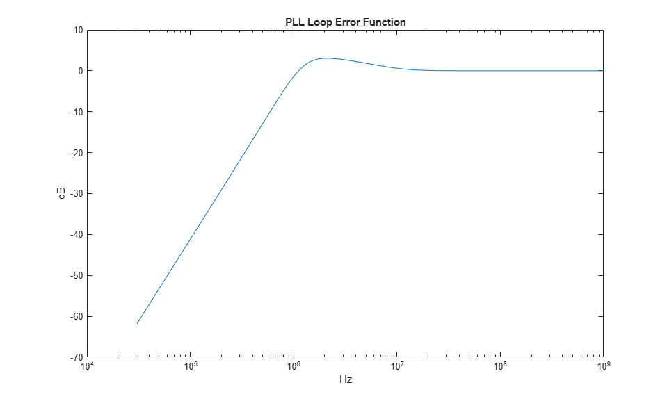
Error function
The PLL control loop is expected to reject phase noise generated inside the PLL itself, such as VCO phase noise. The transfer function between the VCO phase noise and the PLL output is sometimes called the loop error function. Examining this transfer function helps compensate the loop error before it is applied to another noise source.
Create a log-log plot of the PLL loop error function.
figure(3);
semilogx(LoopFrequency,20*log10(abs(LoopEofs)));
title('PLL Loop Error Function');
xlabel('Hz');
ylabel('dB');
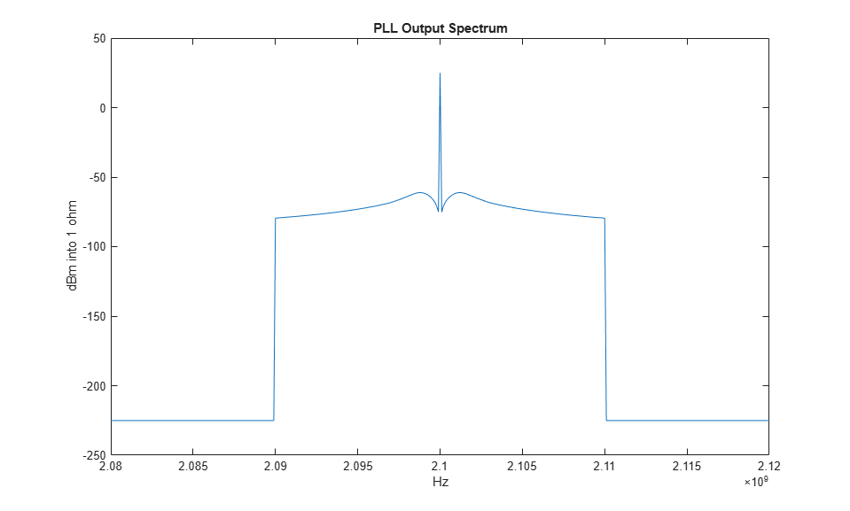
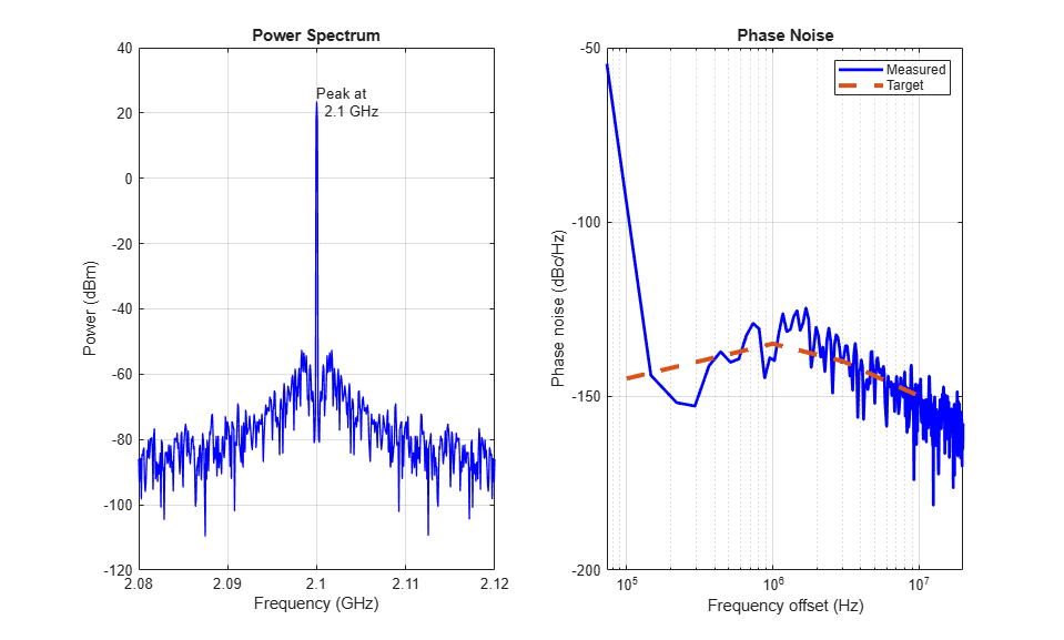
Plot the total expected phase noise at the PLL output.
figure(4);
plot(ExpOutputFrequency,ExpOutputSpectrum);
title('PLL Output Spectrum');
xlabel('Hz');
ylabel('dBm into 1 ohm');
xlim([PllN*CfgRef-2*PllFoffset(end), PllN*CfgRef+2*PllFoffset(end)]);
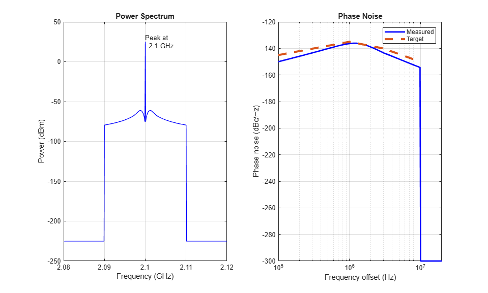
The phaseNoiseMeasure function is a callback function used by the PLL Testbench. It displays the target output phase noise spectral density along with the simulated or expected phase noise spectral density.
To compare the expected output phase noise to a specific design target, define the workspace variable CfgTargetSpectrum. CfgTargetSpectrum consists of two column arrays that specify the target phase noise at the output of the PLL. The first column specifies the frequency offsets in Hz and the second column specifies the corresponding phase noise spectral density in dBc/Hz. The PLL Testbench uses the callback function phaseNoiseMeasure to display the expected and simulated phase noise spectral density.
View the expected PLL output phase noise in units of dBc/Hz.
[~] = phaseNoiseMeasure(ExpOutputFrequency,ExpOutputSpectrum,...
    CfgResBandwidth, CfgTargetSpectrum(:,1).','on','5', ...
    CfgTargetSpectrum(:,2).');
If the loop response is not satisfactory, you might look at more detailed results such as the loop filter transimpedance (LoopZofs) to get additional insights that could help you improve the PLL design.
Run the Simulation
While the configuration process is straightforward, there are many parameters to be configured. Use the configureExamplePLL script to configure the PLL Simulink® model, then execute the model.
configureExamplePll;
SimOut = sim('PllPhaseNoiseExample');
To make the plotting easier, transform the results into the following four workspace variables:
SimInputFrequency- A vector of frequencies for which the input spectrum of the simulation is stored (Hz).SimInputSpectrum- A vector of spectrum values at the reference input to the PLL (dBm into a one ohm load at a resolution bandwidth ofCfgResBandwidth).SimOutputFrequency- A vector of frequencies for which the output spectrum of the simulation is calculated (Hz).SimOutputSpectrum- A vector of simulated spectrum values at the PLL output (dBm into a one ohm load at a resolution bandwidth ofCfgResBandwidth).
Make the results easier to plot from the workspace.
SimInputFrequency = reshape(SimOut.InputFrequency.Data(:,end),1,[]);
SimInputSpectrum = reshape(SimOut.InputSpectrum.Data(:,end),1,[]);
SimOutputFrequency = reshape(SimOut.OutputFrequency.Data(:,end),1,[]);
SimOutputSpectrum = reshape(SimOut.OutputSpectrum.Data(:,end),1,[]);
Compare Expected and Simulated Results
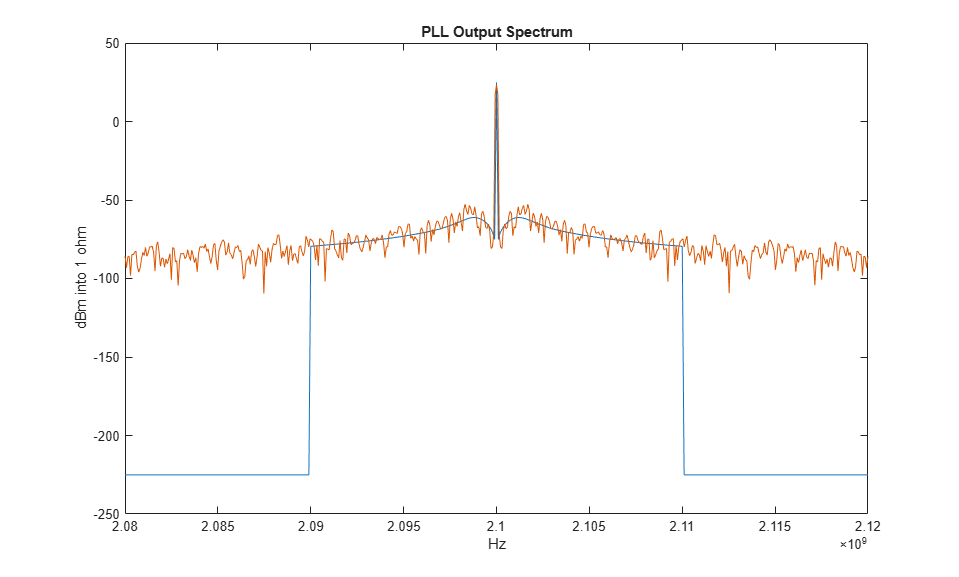
Compare expected and simulated phase noise at the PLL output.
figure(4);
plot(ExpOutputFrequency,ExpOutputSpectrum);
title('PLL Output Spectrum');
xlabel('Hz');
ylabel('dBm into 1 ohm');
xlim([PllN*CfgRef-2*PllFoffset(end), PllN*CfgRef+2*PllFoffset(end)]);
hold on;
plot(SimOutputFrequency,SimOutputSpectrum);
hold off;
View the expected PLL output phase noise in units of dBc/Hz.
[~] = phaseNoiseMeasure(SimOutputFrequency,SimOutputSpectrum,...
    SimOutputFrequency(2)-SimOutputFrequency(1),...
    CfgTargetSpectrum(:,1).','on','5',CfgTargetSpectrum(:,2).');

Save the Configuration and Results
Save the entire workspace, including the system configuration in its current state and the results, to a file. If the WorkspaceFile variable already exists, you can resave the current state to that file. To save to a new file, change the value of WorkspaceFile.
if exist('WorkspaceFile','var')
    save(WorkspaceFile);
end
See Also
Integer N PLL with Single Modulus Prescaler | PLL Testbench | Variable Pulse Delay