EdgeFeed
Description
Use the EdgeFeed
object to create and specify the
FeedDefinitions
property in a parent pcbComponent
object.
Creation
Description
f1=EdgeFeed
creates a defaultEdgeFeed
object.
f1=EdgeFeed(
sets object
properties using one or more name value arguments.name=value
)
Properties
SignalLocations
— Specifies the location to be positively excited
[-0.01,0]
(default) | 1x2 matrix
Specifies the location to be positively excited as a 1x2 matrix in meters.
The first and the second columns correspond to the X and Y coordinates in meters, respectively. This location must lie on the edge of a metal layer. Locations of negative excitation are assumed to lie directly above (+z) and/or below (-z) the location of positive excitation.
Example:
f1=EdgeFeed;f1.SignalLocations=[-0.02,0]
Data Types: double
SignalLayers
— Board Layer for the positive excitation site
1
(default) | scalar
Example: f1=EdgeFeed;f1.SignalLayers=2
Data Types: double
GroundLayers
— Board layers for all negative excitation sites
3 (default) | Nx1 matrix.
Specifies the board layers for all negative excitation sites as a Nx1 matix in meters.
Example: f1=EdgeFeed;f1.GroundLayers=5
Data Types: double
SignalWidths
— Width of the positive excitation site
0.002
(default) | scalar
Specifies the width of the positive excitation site as a scalar, in meters.
Example: f1=EdgeFeed;f1.SignalWidths=0.003
Data Types: double
Examples
Edge Feed setup for a stripline-style pcbComponent
This example shows how to instantiate EdgeFeed objects to excite a pcbComponent in stripline configuration.
Convert the default pcbComponent from microstrip format to stripline format by copying its bottom two layers to the top of the layer stack.
p = pcbComponent; layersTemp = p.Layers; p.BoardThickness = p.BoardThickness * 2; p.Layers = [layersTemp(3), layersTemp(2), layersTemp];
The default FeedLocations property has the correct positions for the two feeds. Save this information to a temporary variable and switch the FeedFormat property to 'FeedDefinitions' to expose the pcbComponent's FeedDefinitions property.
feedsTemp = p.FeedLocations;
p.FeedFormat = 'FeedDefinitions';
Introduce two EdgeFeed objects to excite the strip against both ground planes simultaneously. The second is a copy of the first with an updated position.
f1 = EdgeFeed('SignalLocations', feedsTemp(1, 1:2), 'SignalLayers', 3, 'GroundLayers', [1; 5], 'SignalWidths', p.Layers{3}.Width); f2 = copy(f1); f2.SignalLocations = feedsTemp(2, 1:2);
Write the EdgeFeed objects to the pcbComponent's FeedDefinitions property, then show the pcbComponent and calculate its S-parameters.
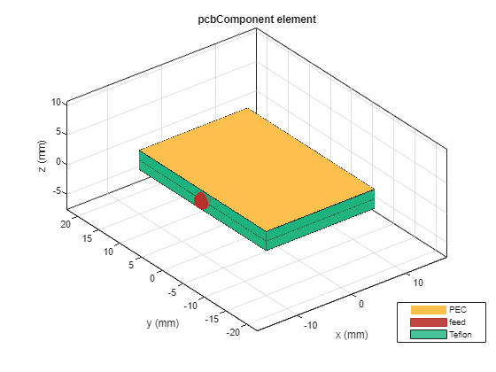
p.FeedDefinitions = [f1 f2]; figure; show(p);
s = sparameters(p, linspace(1e9, 5e9, 10)); figure; rfplot(s);
Version History
Introduced in R2024b
MATLAB Command
You clicked a link that corresponds to this MATLAB command:
Run the command by entering it in the MATLAB Command Window. Web browsers do not support MATLAB commands.
Select a Web Site
Choose a web site to get translated content where available and see local events and offers. Based on your location, we recommend that you select: United States.
You can also select a web site from the following list
How to Get Best Site Performance
Select the China site (in Chinese or English) for best site performance. Other MathWorks country sites are not optimized for visits from your location.
Americas
- América Latina (Español)
- Canada (English)
- United States (English)
Europe
- Belgium (English)
- Denmark (English)
- Deutschland (Deutsch)
- España (Español)
- Finland (English)
- France (Français)
- Ireland (English)
- Italia (Italiano)
- Luxembourg (English)
- Netherlands (English)
- Norway (English)
- Österreich (Deutsch)
- Portugal (English)
- Sweden (English)
- Switzerland
- United Kingdom (English)
Asia Pacific
- Australia (English)
- India (English)
- New Zealand (English)
- 中国
- 日本Japanese (日本語)
- 한국Korean (한국어)