Monitor and Tune ROS 2 Models Using External Mode
Overview of External Mode
External mode allows real-time interaction between Simulink® and deployed ROS 2 nodes on target hardware, making it ideal for rapid prototyping. When you use external mode simulations, a communication channel is established between Simulink on your development computer (host) and the target hardware running the executable file generated by the code build process. This feature facilitates:
Parameter Tuning — Modify parameters and observe immediate effects without restarting the simulation.
Signal Monitoring — Visualize real-time signals in the Sink (Simulink) block or Simulation Data Inspector (SDI) (Simulink) for effective debugging and optimization. XCP-based external mode enables SDI, which provides advanced capabilities for parameter tuning by allowing you to:
Log and compare signals from multiple runs.
Validate and refine models with data visualizations in real time.
Communication Interfaces in External Mode
This table lists the two communication protocols supported by ROS Toolbox.
| Communication Protocols | Purpose | Usage |
|---|---|---|
| XCP on TCP/IP | It is an advanced communication protocol, leveraging the Universal Measurement and Calibration Protocol (XCP) for efficient data exchange and monitoring. | |
| TCP/IP | It is a standard communication protocol for parameter tuning and signal monitoring. | It offers logging capabilities with the Dashboard (Simulink) blocks in addition to Sources (Simulink) and Sink (Simulink) blocks, but does not enable SDI for real-time signal visualization. |
This table below provides a comprehensive comparison of the two communication protocols.
| Feature | XCP on TCP/IP | TCP/IP |
|---|---|---|
| Parameter Tuning |
| Same as XCP on TCP/IP |
| Buffer Customization | User-defined buffer size | Not available |
| Polling Time | Customizable | Fixed |
| SDI | Yes | No |
| Blocks that receive and display signals from target application |
| Same as XCP on TCP/IP except Dashboard library |
Configure External Mode in ROS 2 Models
External mode enables Simulink on your host computer to communicate with a deployed model on your robotics hardware during runtime. For ROS Toolbox, deployed models are ROS 2 nodes running on the target hardware that communicates with Simulink over XCP on TCP/IP or TCP/IP.
To use external mode with ROS Toolbox models:
On the Apps tab, under Control Systems, click Robot Operating System (ROS).
In the Robot Operating System (ROS) dialog box that opens up, select
Robot Operating System 2 (ROS 2)from the ROS Network drop-down list. This opens up the ROS tab in the toolstrip and that shows the specified ROS Network in the Connect section.In the Connect section, set Deploy To to
Remote Device, from the drop-down list. To configure the remote device details such as IP address and user details, selectManage Remote Devicefrom the drop-down list.In the Prepare section, click Hardware Settings to open the model configuration parameters dialog box. In Target Hardware Resources under Hardware board settings, set the External mode parameters. Click OK.
Select the Communication interface from one of these options:
XCP on TCP/IP for advanced data logging and signal monitoring. This is on by default.
TCP for basic parameter tuning.
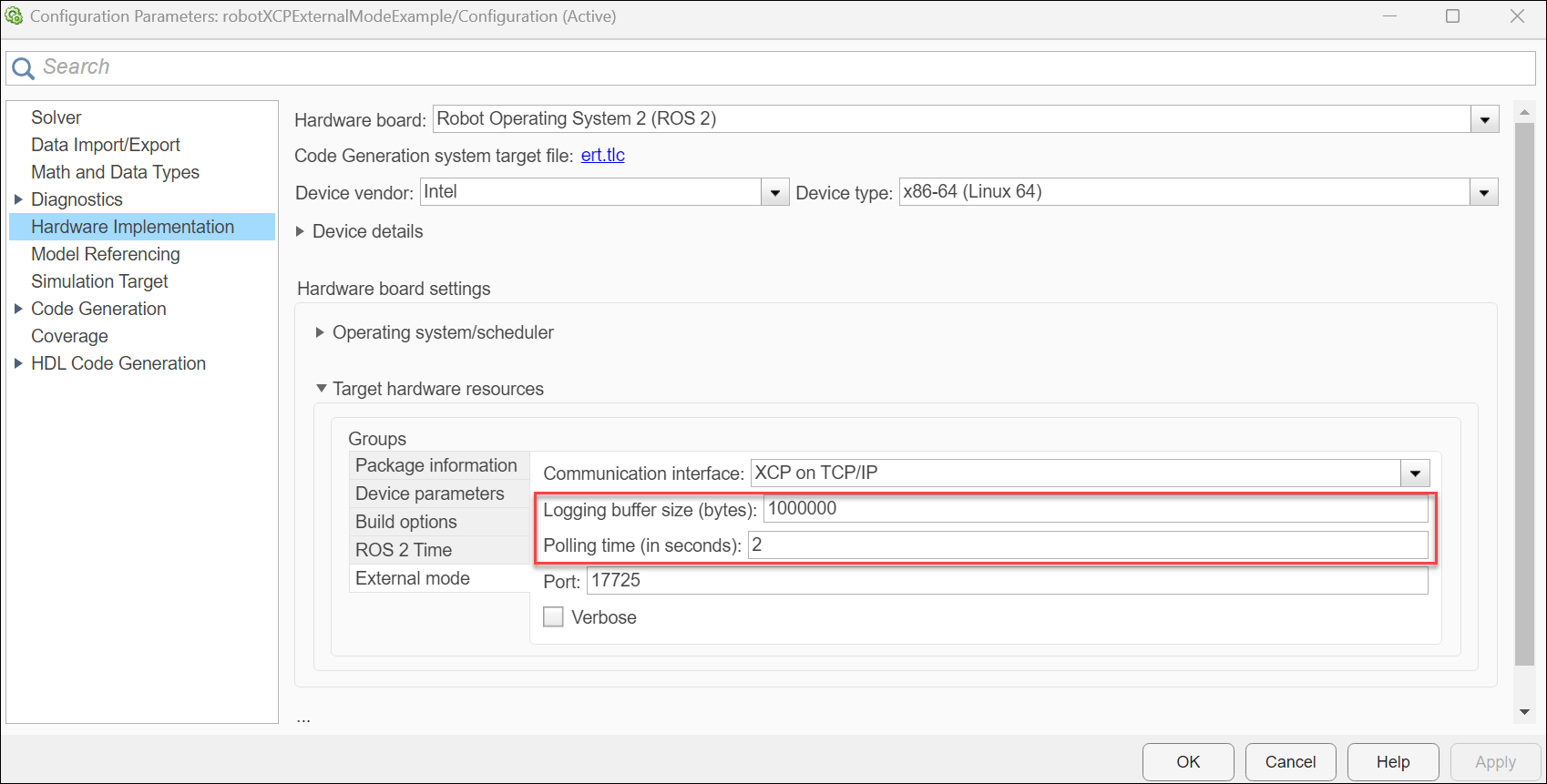
Configure Parameters for XCP on TCP/IP — When you set the Communication interface to XCP-based external mode, the Logging buffer size (bytes) and Polling time (in seconds) parameters become available.
Logging buffer size (bytes): Specify this parameter to set the size of the buffer for logging data during simulation in bytes. The default value is 1,000,000 bytes. Adjust this value based on your signal logging needs.
Polling time (in seconds): Specify this parameter to set the interval to check the status of the external mode simulation, the signal triggering logic, and the current simulation time when signal streaming is disabled or data flow stops in XCP. The default value is 2 seconds. Lower polling times increase responsiveness but can burden the hardware.
Increase polling time if the step function execution time exceeds the current polling time or if real-time task scheduling is slow.
Your model connects to the Device Address specified in the
Connect to ROS Device dialog box, which opens when you select
Manage Remote Device from the Deploy
To drop-down list. The model uses this address to connect to your ROS
device when you deploy it.
Run External Mode Simulations on ROS 2 Feedback Control Robot Model
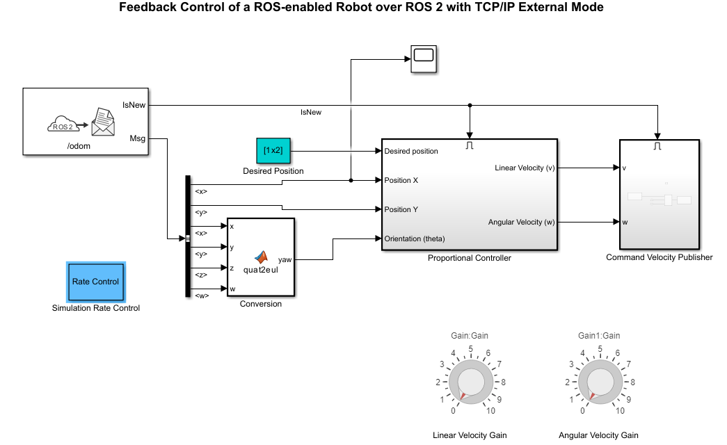
Feedback Control of ROS 2 Robot with TCP/IP External Mode
This example contains the Simulink® model of feedback control robot in ROS 2 that uses TCP/IP communication interface to monitor and tune parameters during simulation.
Prepare Feedback Control Robot Model
1. To run this example, install and set up Docker in your host environment, and create a docker image for Gazebo using the instructions provided in Install and Set Up Docker for ROS, ROS 2, and Gazebo.
2. Refer to the Feedback Control of a ROS-Enabled Robot Over ROS 2 example for instructions to start the docker container and configure and run the Gazebo world. While the Docker container is running, obtain its IP address using the following command in the WSL/Linux/Mac terminal:
$ ifconfig
3. Once the Gazebo world starts running, open and run the ROS 2 feedback control robot model for simulation over TCP/IP in external mode. Configure the model domain ID to 25 to ensure that it runs on the same domain ID as the Gazebo world.
open_system("robotTCPIPExternalModeExample.slx")4. Enable data logging for signals you want to monitor by right-clicking the signal and select Enable Data Logging. Simulink® displays a logged signal indicator for each logged signal, however, you will be unable to view these signals due to inaccessibility to to Simulation Data Inspector.
Use one or more Dashboard (Simulink) blocks such as the Knob block in the model to dynamically tune parameters through dialing during simulation and place Sink blocks like Scope (Simulink) or Display (Simulink) to monitor simulation outputs.
Run Model and Perform Simulation
On the Connect tab, set the Deploy to dropdown to Remote Device, if not set already. Click the Deploy to dropdown and, select Manage Remote Device. This opens the Connect to ROS Device dialog box. In this dialog box, set the following parameters to the given respective values and click OK:
Device address: IP of the Docker container
Username:
userPassword:
password
Now, on the Run On Hardware tab, select Monitor & Tune.
Tune Parameters and Observe Outputs
1. While the simulation is running, modify parameters such as the proportional gain or desired position.
2. Observe the effects in real time through the Sink block such as the Scope.
Stop Simulation
After fine tuning the parameters, click Stop in the Hardware tab.
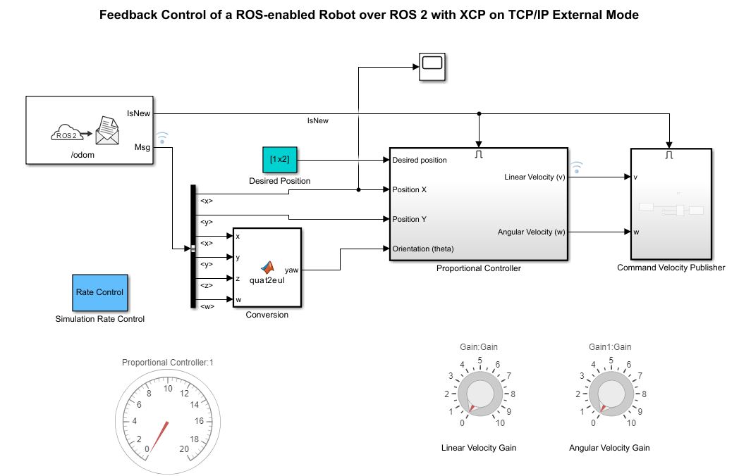
Feedback Control of ROS 2 Robot with XCP-Based External Mode
This example contains the Simulink® model of feedback control robot in ROS 2 that uses XCP-Based communication interface to monitor and tune parameters during simulation.
Prepare Feedback Control Robot Model
1. To run this example, install and set up Docker in your host environment, and create a docker image for Gazebo using the instructions provided in Install and Set Up Docker for ROS, ROS 2, and Gazebo.
2. Refer to the Feedback Control of a ROS-Enabled Robot Over ROS 2 example for instructions to start the docker container and configure and run the Gazebo world. While the Docker container is running, obtain its IP address using the following command in the WSL/Linux/Mac terminal:
$ ifconfig
3. Once the Gazebo world starts running, open and run the ROS 2 feedback control robot model for simulation over XCP on TCP/IP in external mode. Configure the model domain ID to 25 to ensure that it runs on the same domain ID as the Gazebo world.
open_system("robotXCPExternalModeExample.slx")4. Enable data logging for signals you want to monitor by right-clicking the signal and select Enable Data Logging. Simulink® displays a logged signal indicator for each logged signal and you can view them in the Simulation Data Inspector(SDI).
5.Use one or more Dashboard (Simulink) blocks such as the Knob block in the model to dynamically tune parameters through dialing during simulation. Connect Display (Simulink) block and mark the signals connected to them for logging.
Run Model and Perform Simulation
On the Connect tab, set the Deploy to dropdown to Remote Device, if not set already. Click the Deploy to dropdown and, select Manage Remote Device. This opens the Connect to ROS Device dialog box. In this dialog box, set the following parameters to the given respective values and click OK:
Device address: IP of the Docker container
Username:
userPassword:
password
Now, on the Run On Hardware tab, select Monitor & Tune.
Tune Parameters and Observe Outputs
Open the SDI for detailed analysis. Click the Simulation Data Inspector button to open the Inspect pane. The Inspect pane lists all logged signals in rows, organized by simulation run. You can expand or collapse any of the runs to view the signals in a run. For more information on signal grouping, see Signal Grouping section in Configure the Simulation Data Inspector (Simulink).
We recommend you to use simulation Data Inspector (SDI) rather than using Sink blocks for the following reasons:
Streaming data to SDI does not store data in memory, making more efficient use of the memory available on the hardware. Sink blocks such as Scope (Simulink) stores data in buffers before sending the data to the host.
Using SDI, you can stream signals from top models and reference models simultaneously. Scope blocks can only log signals from a top-level model.
Adjust Parameters
Modify parameters like buffer size or polling interval in the Hardware board settings under Hardware Implementation for subsequent runs.
Stop Simulation
After fine tuning the parameters, click Stop in the Hardware tab.