Implement Automatic Gain Control for RF Receiver
This example shows how to leverage model reference hierarchies and component-based modeling principles when incorporating an RF Blockset™ circuit envelope model into a system that implements baseband signal processing, communications algorithms, and adaptive architectures around an RF network. To illustrate these concepts, this example designs and implements an automatic gain control (AGC) algorithm for an RF direct-conversion receiver (DCR) in a context similar to that of the ZigBee®-like application explored in Top-Down Design of RF Receiver.
In addition, this example demonstrates the use of model references, modeling hierarchies, protected models, variants for modular development, accelerated simulation, and overall rapid design iteration. For more information about these concepts, see Model Reference Behavior and Capabilities and Component-Based Modeling in Simulink.
Prerequisites
This example is configured to use the non-protected referenced model, "RFDCR.slx", created in Part 1 of this example series: Design RF Direct-Conversion Receiver.
Alternatively, you can opt to use the protected version of the same referenced model, "RFDCR.slxp", from Part 2 of this example series: Protect Circuit Envelope Model. To use the protected model instead of the non-protected model in the current example, first run the previous example in the same platform and MATLAB® version, and then copy the generated "RFDCR.slxp" file into the working folder of the current example. The top-level model's PostLoadFcn callback is configured to automatically use the SLXP file, if it is available, instead of the SLX file for the model reference.
Note the following considerations for protected models:
To generate a protected model, you need a Simulink® Coder™ license.
SLXP files are platform- and release-specific.
RF Blockset Circuit Envelope supports neither cross-release nor cross-platform protected model workflows.
ZigBee-Like System Containing RF DCR and Subject to Strong Interference
The top-level system consists of the following components:
Baseband transmitter used to generate a ZigBee-like waveform spectrally representative of signals that conform to the IEEE® 802.15.4 standard
Wideband interferer used to generate a WCDMA-like, in-band but out-of-channel blocker spectrally representative of interfering signals noncompliant with the standard
Circuit envelope model of an RF DCR
AGC algorithm implemented via a MATLAB Function block to supply the variable gain and variable attenuation control signals to the RF DCR
Peak detector used by the AGC feedback loop to regulate the fast response, which decreases gain and increases attenuation when the peak power exceeds a prespecified threshold
Average power meter used by the AGC feedback loop to regulate the slow response, which adjusts gain and attenuation to steadily bring the average power and signal-to-noise ratio (SNR) to the target levels
Analog-to-digital converter (ADC) used to convert the baseband analog signal output by the RF receiver into baseband digital signals consumed by downstream communications and digital signal processing
Baseband receiver that receives and processes the 802.15.4 waveform and computes the chip error rate (ChER) system-level performance metric.
To begin, specify the baseband and RF parameters that are required for simulation. Note that vgaIIP2 and vgaIIP3 are tunable parameters of the model for the RF DCR. The remaining parameters are associated with various baseband components in the top-level system.
% Baseband parameters
bitRate = 250e3;
spf = 4;  % samples per frame
bps = 4;  % bits per ZigBee symbol
sps = 16; % samples per OQPSK symbol
cps = 32; % chips per ZigBee symbol
chipRate = bitRate*cps/bps;

% RF parameters
oversampling = 4; % no out-of-band signal
vgaIIP2 = 50;     % IIP2 of RF receiver's VGA
vgaIIP3 = 30;     % IIP3 of RF receiver's VGA
To use a protected model containing Circuit Envelope blocks, you first need to ensure that the necessary RF Blockset libraries and dependencies are loaded in MATLAB®. Note that you only need to do this once per MATLAB session, but you must do this before the first time you use a protected model containing Circuit Envelope blocks in that MATLAB session. Execute the following command to preload the Circuit Envelope Utilities library and to configure the RF Blockset environment.
open_system simrfV2util1

Open the top-level model. Note that the model contains interactive controls, which you can use to quickly modify it.
model = "RFDCRWithAGC";
open_system(model)

Reference Model of RF DCR
Open the subsystem containing the referenced model of the RF DCR.
subsystemDCR = model + ...
    "/Circuit Envelope Model of Direct Conversion Receiver";
blockModelReference = subsystemDCR + "/Model";
open_system(subsystemDCR)
If the Model block references a protected model, it is indicated as such by a shield badge on the bottom-left corner of the block. Furthermore, the protected model has predefined sample rates as well as fixed input and output signal dimensions, given that it is precompiled. To review the protected model's interface specifications, you can right-click on the shield badge and select Display Report or see Protect Circuit Envelope Model.
The model of the RF DCR is designed to work with framed signals of size 256 and period 8e-6 seconds at its input and output ports. Consequently, to implement baseband system designs with different frame sizes and frame rates, you might need to use Unbuffer, Buffer, and Rate Transition blocks in the top-level system to correctly interface with the referenced model for the RF system. While a full treatment of this is out of scope for this example, the top-level model already includes these blocks, although some of them are commented out.

Use Variants to Switch Between AGC and Fixed Mode Implementations
The top-level model also makes use of Simulink variants. In general, you can use variant subsystems and Simulink variant capabilities to create flexible models with built-in variabilities to efficiently manage and compare various designs. In this example model, you can quickly enable or disable the AGC algorithm as per the following steps. First, right-click on the variant badge on the bottom-left corner of the Variant Subsystem block. Then, set Label Mode Active Choice as desired.
subsystemAGC = model + "/Variable Gain and Variable Attenuation";
open_system(subsystemAGC)

The AGC dynamically adjusts the gain and attenuation of the DCR to maximize the SNR. It amplifies the output power from the RF network to stay within the dynamic range of the ADC, and it attenuates the incoming power to the RF network to prevent saturation and overload of the RF front-end. In contrast, without the AGC the gain and attenuation are fixed and require manual retuning to maximize the SNR. In this example, the AGC maintains the variable gain between –10 dB to 40 dB. It also maintains the variable attenuation between 0 dB to 60 dB. You can enable the AGC by setting the active variant in the variant subsystem.
set_param(subsystemAGC,LabelModeActiveChoice="With AGC")
activeVariant = get_param(subsystemAGC,"CompiledActiveChoiceBlock");
open_system(activeVariant)

When the AGC is disabled, the fixed value set for the variable gain is 40 dB, and the fixed value set for the variable attenuation is 0 dB. You can disable the AGC by setting the active variant in the variant subsystem.
set_param(subsystemAGC,LabelModeActiveChoice="Without AGC")
activeVariant = get_param(subsystemAGC,"CompiledActiveChoiceBlock");
open_system(activeVariant)

Store Block Paths to Tune Signal and Interferer Levels and View Scopes
Store the paths to the blocks used to adjust the power levels of the transmitter and interferer. Each of these blocks applies a dB gain to its input, as specified by its dB parameter. At 0 dB gain, the nominal power levels for both the transmitter and the interferer are –100 dBm. You can interactively tune the dB gains from within the Simulink Editor, or you can programmatically set them.
blockGainTransmitter = model + "/dB Gain Transmitter";
blockGainInterferer = model + "/dB Gain Interferer";
In preparation for model simulation, open the scopes and reopen the top-level system so that you can view the results live during simulation. Store the block paths of the scopes so that you can continue to reopen and examine the scopes later in this example after each simulation run.
blockScope = model + "/Scope";
blockRxSpectrum = model + "/Rx Spectrum";
open_system(model)
open_system(blockRxSpectrum)
open_system(blockScope)

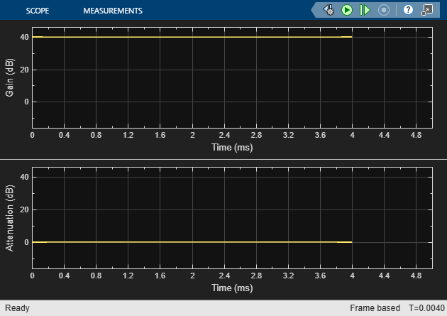
Simulate Model with AGC for Sensitivity Level Input and Weak Interferer
As per the design of the DCR in Design RF Direct-Conversion Receiver, the minimum signal power required to operate the receiver is around –100 dBm. In the top-level system, the baseband transmitter starts at –100 dBm, which is the sensitivity level of the DCR. The interferer is also set to –100 dBm and is thus a weak interferer. As a result, the ChER is essentially determined by the noise floor. Given the low input power levels, the AGC maximizes the variable gain to 40 dB and minimizes the variable attenuation to 0 dB.
set_param(subsystemAGC,LabelModeActiveChoice="With AGC")
set_param(blockGainTransmitter,dB="0")
set_param(blockGainInterferer,dB="0")
Simulate the model, using the evalc function to wrap around the call to the sim function to suppress the verbose display of the build progress and compiler output diagnostics. Examine the performance metrics, the spectrum of the received signal after the ADC, and the evolution of the variable gain and attenuation as regulated by the AGC. For your convenience, the model automatically resets the ChER metrics after 2 ms and recomputes it from 2–4 ms. This provides enough time for the AGC-controlled variable gain to stabilize, and so the final reported ChER is not affected by the startup dynamics of the model.
[~] = evalc('simOut = sim(model,StopTime="4E-3");');
open_system(blockRxSpectrum)
open_system(blockScope)
disp(table(simOut.ChER.Data(end,2),simOut.ChER.Data(end,3), ...
    round(simOut.ChER.Data(end,1)*100,2), ...
    VariableNames=["NumErrors" "NumChipsTotal" "ChER (%)"]))
    NumErrors    NumChipsTotal    ChER (%)
    _________    _____________    ________

       331           4032           8.21


Without the AGC, the variable gain stays at 40 dB, and the variable attenuation stays at 0 dB. This matches the respective levels to which the variable gain and attenuation settle in the presence of the AGC, so you can expect similar system performance with vs. without the AGC. Although this example does not explicitly show it, you can rerun this simulation with the AGC disabled to confirm the same.
Increase Input Power Above Noise Floor and Simulate Model with AGC
Increase the input power by 10 dB, which is well above the noise floor. Meanwhile, keep the interferer power the same at –100 dBm. The AGC still maximizes the variable gain to 40 dB and minimizes the variable attenuation to 0 dB. The overall input power is still far from the DCR's saturation level. Accordingly, the ChER is close to zero.
set_param(subsystemAGC,LabelModeActiveChoice="With AGC")
set_param(blockGainTransmitter,dB="10")
set_param(blockGainInterferer,dB="0")

[~] = evalc('simOut = sim(model,StopTime="4E-3");');
open_system(blockRxSpectrum)
open_system(blockScope)
disp(table(simOut.ChER.Data(end,2),simOut.ChER.Data(end,3), ...
    round(simOut.ChER.Data(end,1)*100,2), ...
    VariableNames=["NumErrors" "NumChipsTotal" "ChER (%)"]))
    NumErrors    NumChipsTotal    ChER (%)
    _________    _____________    ________

        1            4032           0.02


Simulate Model with AGC in Presence of Strong Interferer
Increase the interferer power by 50 dB, thus creating substantial in-band blocking, capable of driving the DCR into saturation. In response, the AGC reduces the variable gain to 26 dB, lower than the maximum of 40 dB. The ChER worsens, but the degradation is mitigated due to the AGC.
set_param(subsystemAGC,LabelModeActiveChoice="With AGC")
set_param(blockGainTransmitter,dB="10")
set_param(blockGainInterferer,dB="50")

[~] = evalc('simOut = sim(model,StopTime="4E-3");');
open_system(blockRxSpectrum)
open_system(blockScope)
disp(table(simOut.ChER.Data(end,2),simOut.ChER.Data(end,3), ...
    round(simOut.ChER.Data(end,1)*100,2), ...
    VariableNames=["NumErrors" "NumChipsTotal" "ChER (%)"]))
    NumErrors    NumChipsTotal    ChER (%)
    _________    _____________    ________

       771           4032          19.12


Disable AGC and Compare System Performance
Disable the AGC and rerun the simulation. In absence of the AGC, the strong interferer drives the DCR into saturation, as the system does not have a mechanism to adapt to and avoid this situation. The variable gain remains at 40 dB, and the variable attenuation remains at 0 dB. As a result, the ChER suffers from severe degradation.
set_param(subsystemAGC,LabelModeActiveChoice="Without AGC")
set_param(blockGainTransmitter,dB="10")
set_param(blockGainInterferer,dB="50")

[~] = evalc('simOut = sim(model,StopTime="4E-3");');
open_system(blockRxSpectrum)
open_system(blockScope)
disp(table(simOut.ChER.Data(end,2),simOut.ChER.Data(end,3), ...
    round(simOut.ChER.Data(end,1)*100,2), ...
    VariableNames=["NumErrors" "NumChipsTotal" "ChER (%)"]))
    NumErrors    NumChipsTotal    ChER (%)
    _________    _____________    ________

      1933           4032          47.94