simscape.addConnection
Syntax
Description
simscape.addConnection(
adds a connection line between two ports that belong to Simscape™ blocks. Supported block types include:block1,port1,block2,port2)
Simscape blocks in the Foundation and Utilities libraries and in the add-on product libraries
Custom Simscape blocks
Simscape Multibody™ blocks
Subsystems containing Simscape or Simscape Multibody blocks
Connection rules are the same as for connecting ports on the model canvas. For example, you can connect:
Conserving ports that belong to the same domain.
Untyped conserving ports, such as a connection port on a Solver Configuration block or Connection Port block that does not have prior connections, to any conserving port on another block. Once a conserving port becomes typed, that is, connected to another port of a specific domain type, you can connect it only to other ports of the same type.
Physical signal output and input ports. The signal sizes must be the same.
Bus ports of two different Simscape Bus blocks with matching sizes and types, for example, when both ports have the same rigid interface type.
The connection order does not matter. Conserving connections are nondirectional. Physical signal connections establish a connection line from the output to the input port regardless of the order that you specify them in the command syntax.
The ports being connected must be either both at the top level of the model hierarchy or both in the same subsystem. There is also a special syntax option for Connection Port blocks that simplifies adding connections across subsystem boundaries. For more information, see Connect Blocks Across Subsystem Boundaries.
Examples
In this example, you create a new Simscape model, then programmatically add two electrical blocks and connect them using their port names.
Create a new model, named MyModel.
sscnew("MyModel");
Add and position a Resistor block.
add_block("fl_lib/Electrical/Electrical Elements/Resistor","MyModel/Resistor");
set_param("MyModel/Resistor","position",[305,95,345,125]);
Add and position an Inductor block.
add_block("fl_lib/Electrical/Electrical Elements/Inductor","MyModel/Inductor");
set_param("MyModel/Inductor","position",[470,150,510,180]);
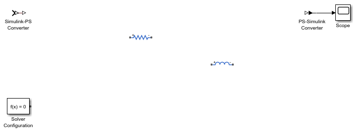
The model, with the two added blocks, looks like this.
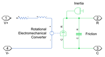
Electrical blocks have ports labeled + and
-. However, port names in this case are different than the port
labels on the model canvas. Port names are p and
n, respectively, corresponding to the node names in the underlying
component source. To determine the port names of a block, use the simscape.connectionPortProperties function. Also, after you enter the name
of a block to connect, tab completion lists the valid port names.
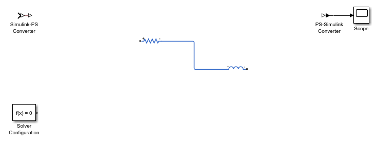
Connect the negative port of the Resistor block to the positive port of the Inductor block.
simscape.addConnection("MyModel/Resistor","n","MyModel/Inductor","p")
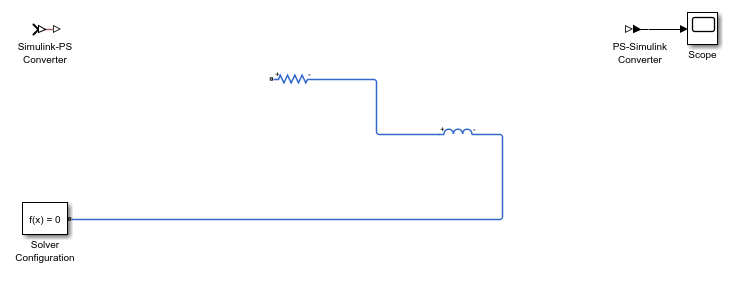
Connect the negative port of the Inductor block to the port of the Solver Configuration block.
simscape.addConnection("MyModel/Inductor","n","MyModel/Solver Configuration","port")
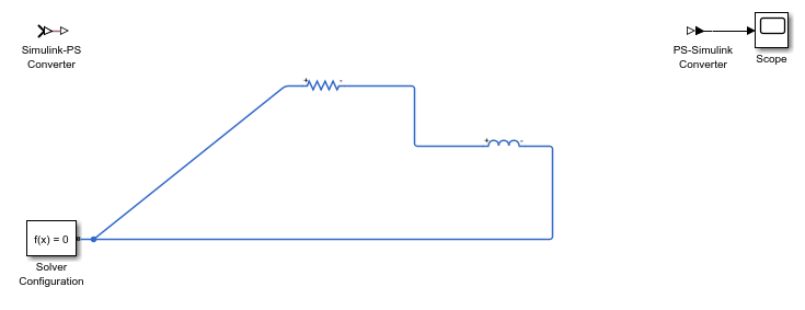
By default, the automatic line routing is on. To turn it off, specify the additional argument.
simscape.addConnection("MyModel/Resistor","p","MyModel/Solver Configuration","port","autorouting","off")
This example illustrates different syntax options for Connection Port blocks and also shows useful tab completion techniques.
Open the Permanent Magnet DC Motor example model.
openExample('simscape/PermanentMagnetDCMotorExample')
Delete the connection line between the DC Voltage block and the DC Motor subsystem.
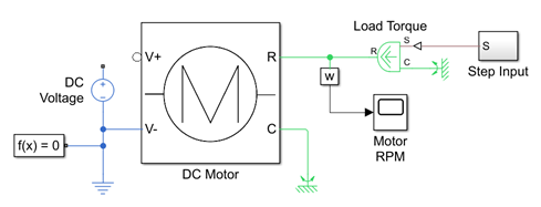
Open the DC Motor subsystem and delete the connection line between the Connection Port block V+ and the Resistor block.
To facilitate entering the names of the blocks to connect, define workspace variables corresponding to the block names in the model.
source = "PermanentMagnetDCMotor/DC Voltage";
subsystem = "PermanentMagnetDCMotor/DC Motor";
resistor = "PermanentMagnetDCMotor/DC Motor/Rotor Resistance";
This technique is helpful because tab completion recognizes workspace variables.
Restore the connection line between the DC Voltage block and the DC Motor subsystem, at the top level of the model diagram.
simscape.addConnection(source,"p",subsystem,"V+")
Notice that when you specify subsystem as the second block, tab
completion lists only the electrical ports of the DC Motor subsystem,
V+ and V-. The reason is that ports
R and C are connected to mechanical rotational
blocks inside the DC Motor subsystem and therefore are not the valid type
for creating an electrical connection.

Use the same syntax to restore the connection from the Resistor block inside the DC Motor subsystem.
simscape.addConnection(resistor,"p",subsystem,"V+")
This is a special syntax that lets you conveniently connect blocks across the subsystem boundaries, by referring to the Connection Port block port by the same syntax both from inside and outside of the subsystem.
From inside the subsystem, you can also use the regular syntax to refer to the Connection Port block port. In other words, when making connections inside a subsystem, these two syntaxes are equivalent:
"PermanentMagnetDCMotor/DC Motor/V+","port"
"PermanentMagnetDCMotor/DC Motor","V+"

Input Arguments
Limitations
Two-way connection ports are not supported.
Version History
Introduced in R2025a