Use Parameter Configuration in Analysis
Parameter configuration allows Simulink®
Design Verifier™ to assess the impact of parameter ranges along with the default value
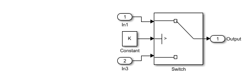
during the analysis. Consider an example model that illustrates the impact of parameter
configuration on analysis outcomes. The model features a switch block with its control
port conditioned on > 0 and is influenced by a calibration parameter
K that has a value of 0 in the base workspace.
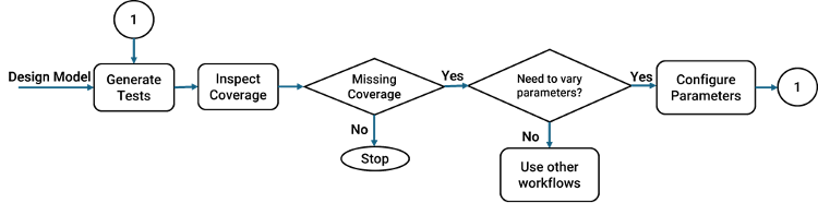
When you configure parameters depends on which workflow you use.
Configure parameters when you generate test cases for coverage - In this workflow, you vary the parameters after assessing whether the parameter values impact model coverage objectives.
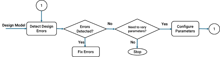
Configure parameters during design error detection analysis - In this workflow you vary parameters after detecting design errors to check if any parameter values result in a run-time error in the logic that uses these values.
The table below showcases how the analysis results vary with parameter configurations:
Parameter K with value
0 in base workspace | No Parameter Configuration specified | Parameter Configuration specified with
K in interval
[-1,1] |
| Analysis result |
|
|
| Test cases | Parameters retain same value as specified in base workspace for all test cases. | Parameter values are reported along with input values, and they may vary from one test case to another. |
The figure below shows the three basic steps involved in parameter configuration:
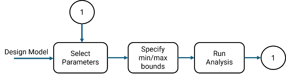
Select Parameters: Parameters are defined using
Simulink.Parametervariables for calibration. You have the option to either select the parameters manually to configure or let Simulink Design Verifier automatically detect and configure these parameters. For more information, see Select Constraints for Parameter Configuration.Specify Ranges: You can define ranges (maximum or minimum values) for the selected parameters. For a
Simulink.Parametervariable, the default range is determined by the maximum or minimum values.Run Analysis: The Simulink Design Verifier analysis uses these values to produce the results. The generated test cases include the parameter values in addition to the necessary inputs to achieve the desired coverage.
Limitations for Parameter Configurations
The following table illustrates the cases where Simulink Design Verifier does not support specifying the parameter configuration:
| Parameters Based on | Limitations |
Location | Simulink Design Verifier does not support parameter configuration for parameters that are:
|
Data types | Simulink Design Verifier does not support parameter configuration for parameters that are:
|
| Block types | Simulink Design Verifier does not support parameter configuration for parameters from these blocks:
|
Note
Simulink Design Verifier does not support parameter configuration for parameters which are present only in the replacement model. The analysis may report dead logic if you introduce new parameters in the replacement model.
See Also
Create Parameter Configuration for Simulink Design Verifier Analysis